Hydraulic filters are essential components of aircraft hydraulic systems because they remove contamination before it can damage pumps, valves, actuators, and other precision components. By trapping dirt, metal particles, and other debris, filters help maintain system reliability, reduce wear, and prevent hydraulic failures. Aircraft hydraulic systems may use several different types of filters and indicators depending on the location and purpose of the filter within the system.
A filter is a screening or straining device used to clean hydraulic fluid, preventing foreign particles and contaminating substances from remaining in the system. [Figure 1] If such objectionable material were not removed, the entire hydraulic system of the aircraft could fail through the breakdown or malfunctioning of a single unit of the system.
 |
| Figure 1. Filter module components |
The hydraulic fluid holds in suspension tiny particles of metal that are deposited during the normal wear of selector valves, pumps, and other system components. Such minute particles of metal may damage the units and parts through which they pass if they are not removed by a filter. Since tolerances within the hydraulic system components are quite small, it is apparent that the reliability and efficiency of the entire system depends upon adequate filtering.
Filters may be located within the reservoir, in the pressure line, in the return line, or in any other location the designer of the system decides that they are needed to safeguard the hydraulic system against impurities. Modern design often uses a filter module that contains several filters and other components. [Figure 2]
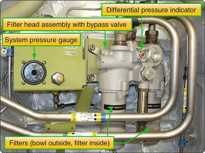 |
| Figure 2. A transport category filter module with two filters |
There are many models and styles of filters. Their position in the aircraft and design requirements determine their shape and size. Most filters used in modern aircraft are of the inline type. The inline filter assembly consists of three basic units: the head assembly, bowl, and element. The head assembly is secured to the aircraft structure and connecting lines. Within the head, there is a bypass valve that routes the hydraulic fluid directly from the inlet to the outlet port if the filter element becomes clogged with foreign matter. The bowl is the housing that holds the element to the filter head and is removed when element removal is required.
The element may be a micron-type, porous-metal, or magnetic type. The micron element is made of a specially treated paper and is normally thrown away when removed. The porous metal and magnetic filter elements are designed to be cleaned by various methods and replaced in the system.
Micron-Type Filters
A typical micron-type filter assembly utilizes an element made of specially treated paper that is formed in vertical convolutions (wrinkles). An internal spring holds the elements in shape. The micron element is designed to prevent the passage of solids greater than 10 microns (0.000394 inch) in size. [Figure 3]
In the event that the filter element becomes clogged, the spring-loaded relief valve in the filter head bypasses the fluid after a differential pressure of 50 psi has been built up. Hydraulic fluid enters the filter through the inlet port in the filter body and flows around the element inside the bowl. Filtering takes place as the fluid passes through the element into the hollow core, leaving the foreign material on the outside of the element.
 |
| Figure 3. Size comparison in microns |
Maintenance of Filters
Maintenance of filters is relatively easy. It mainly involves cleaning the filter and element or cleaning the filter and replacing the element. Filters using the micron-type element should have the element replaced periodically according to applicable instructions. Since reservoir filters are of the micron type, they must also be periodically changed or cleaned. For filters using other than the micron-type element, cleaning the filter and element is usually all that is necessary. However, the element should be inspected very closely to ensure that it is completely undamaged. The methods and materials used in cleaning all filters are too numerous to be included in this text. Consult the manufacturer’s instructions for this information.
When replacing filter elements, be sure that there is no pressure on the filter bowl. Protective clothing and a face shield must be used to prevent fluid from contacting the eyes. Replace the element with one that has the proper rating. After the filter element has been replaced, the system must be pressure tested to ensure that the sealing element in the filter assembly is intact.
In the event of a major component failure, such as a pump, consideration must be given to replacing the system filter elements, as well as the failed component.
Filter Bypass Valve
Filter modules are often equipped with a bypass relief valve. The bypass relief valve opens if the filter clogs, permitting continued hydraulic flow and operation of aircraft systems. Dirty hydraulic fluid is preferable to no flow at all. Figure 4 shows the principle of operation of a filter bypass valve. The ball valve opens when the filter becomes clogged and the pressure over the filter increases.
 |
| Figure 4. Filter bypass valve |
Filter Differential Pressure Indicators
The extent to which a filter element is loaded can be determined by measuring the drop in hydraulic pressure across the element under rated flow conditions. This drop, or differential pressure, provides a convenient means of monitoring the condition of installed filter elements and is the operating principle used in the differential pressure or loaded-filter indicators found on many filter assemblies.
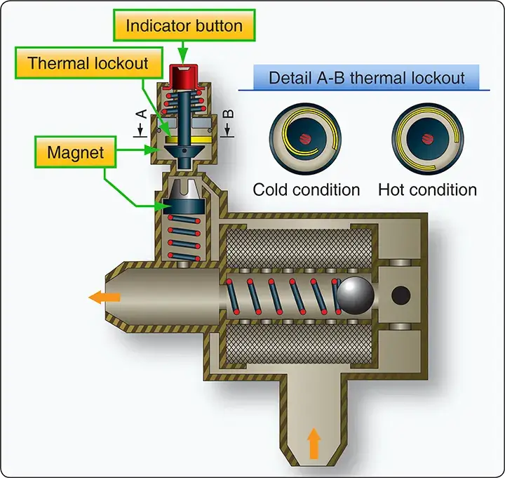
Differential pressure indicating devices have many configurations, including electrical switches, continuous-reading visual indicators (gauges), and visual indicators with memory. Visual indicators with memory usually take the form of magnetic or mechanically latched buttons or pins that extend when the differential pressure exceeds that allowed for a serviceable element. [Figure 12-18, top]
When this increased pressure reaches a specific value, inlet pressure forces the spring-loaded magnetic piston downward, breaking the magnetic attachment between the indicator button and the magnetic piston. This allows the red indicator to pop out, signifying that the element must be cleaned. The button or pin, once extended, remains in that position until manually reset and provides a permanent (until reset) warning of a loaded element. This feature is particularly useful where it is impossible for an operator to continuously monitor the visual indicator, such as in a remote location on the aircraft.
Some button indicators have a thermal lockout device incorporated in their design that prevents operation of the indicator below a certain temperature. The lockout prevents the higher differential pressure generated at cold temperatures by high fluid viscosity from causing a false indication of a loaded filter element.
Differential pressure indicators are a component part of the filter assembly in which they are installed and are normally tested and overhauled as part of the complete assembly. With some model filter assemblies, however, it is possible to replace the indicator itself without removal of the filter assembly if it is suspected of being inoperative or out of calibration. It is important that the external surfaces of button-type indicators be kept free of dirt or paint to ensure free movement of the button. Indications of excessive differential pressure, regardless of the type of indicator employed, should never be disregarded.
All such indications must be verified and action taken, as required, to replace the loaded filter element. Failure to replace a loaded element can result in system starvation, filter element collapse, or the loss of filtration where bypass assemblies are used. Verification of loaded filter indications is particularly important with button-type indicators as they may have been falsely triggered by mechanical shock, vibration, or cold start of the system. Verification is usually obtained by manually resetting the indicator and operating the system to create a maximum flow demand ensuring that the fluid is at near normal operating temperatures.