Hydraulic pumps are the heart of an aircraft hydraulic system because they provide the force needed to move fluid throughout the system. Aircraft may use hand pumps, engine-driven pumps, electrically driven pumps, air-driven pumps, or ram air turbine (RAT)-driven pumps depending on the aircraft design and operating conditions. Hydraulic pumps may also be classified as constant-displacement or variable-displacement types, each with different operating characteristics and applications.
All aircraft hydraulic systems have one or more power-driven pumps and may have a hand pump as an additional unit when the engine-driven pump is inoperative. Power-driven pumps are the primary source of energy and may be either engine driven, electric motor driven, or air driven. As a general rule, electrical motor pumps are installed for use in emergencies or during ground operations. Some aircraft can deploy a ram air turbine (RAT) to generate hydraulic power.
Hand Pumps
The hydraulic hand pump is used in some older aircraft for the operation of hydraulic subsystems and in a few newer aircraft systems as a backup unit. Hand pumps are generally installed for testing purposes, as well as for use in emergencies. Hand pumps are also installed to service the reservoirs from a single refilling station. The single refilling station reduces the chances for the introduction of fluid contamination.
Several types of hand pumps are used: single action, double action, and rotary. A single action hand pump draws fluid into the pump on one stroke and pumps that fluid out on the next stroke. It is rarely used in aircraft due to this inefficiency.
Double-action hand pumps produce fluid flow and pressure on each stroke of the handle. [Figure 1] The double-action hand pump consists essentially of a housing that has a cylinder bore and two ports, a piston, two spring-loaded check valves, and an operating handle. An O-ring on the piston seals against leakage between the two chambers of the piston cylinder bore. An O-ring in a groove in the end of the pump housing seals against leakage between the piston rod and housing.
 |
| Figure 1. Double action hand pump |
When the piston is moved to the right, the pressure in the chamber left of the piston is lowered. The inlet port ball check valve opens and hydraulic fluid is drawn into the chamber. At the same time, the rightward movement of the piston forces the piston ball check valve against its seat. Fluid in the chamber to the right of the piston is forced out of the outlet port into the hydraulic system.
When the piston is moved to the left, the inlet port ball check valve seats. Pressure in the chamber left of the piston rises, forcing the piston ball check valve off of its seat. Fluid flows from the left chamber through the piston to the right chamber. The volume in the chamber right of the piston is smaller than that of the left chamber due to the displacement created by the piston rod. As the fluid from the left chamber flows into the smaller right chamber, the excess volume of fluid is forced out of the outlet port to the hydraulic system.
A rotary hand pump may also be employed. It produces continuous output while the handle is in motion. Figure 2 shows a rotary hand pump in a hydraulic system.
 |
| Figure 2. Rotary hand pump |
Power-Driven Hydraulic Pumps
Many of the power driven hydraulic pumps of current aircraft are of variable delivery, compensator-controlled type. Constant delivery pumps are also in use. Principles of operation are the same for both types of pumps. Modern aircraft use a combination of engine-driven power pumps, electrical-driven power pumps, air-driven power pumps, power transfer units (PTU), and pumps driven by a RAT.
For example, large aircraft such as the Airbus A380 have three hydraulic systems, eight engine-driven pumps, and three electrically driven pumps. The Boeing 777 has three hydraulic systems with two engine driven pumps, four electrical driven pumps, two air driven pumps, and a hydraulic pump motor driven by the RAT. [Figure 3 and 4]
 |
| Figure 3. Engine-driven pump |
 |
| Figure 4. Electrically-driven pump |
Classification of Pumps
All pumps may be classified as either positive displacement or nonpositive displacement. Most pumps used in hydraulic systems are positive displacement. A nonpositive displacement pump produces a continuous flow. However, because it does not provide a positive internal seal against slippage, its output varies considerably as pressure varies. Centrifugal and propeller pumps are examples of nonpositive-displacement pumps. If the output port of a nonpositive-displacement pump was blocked off, the pressure would rise and output would decrease to zero.
Although the pumping element would continue moving, flow would stop because of slippage inside the pump. In a positive-displacement pump, slippage is negligible compared to the pump’s volumetric output flow. If the output port were plugged, pressure would increase instantaneously to the point that the pump pressure relief valve opens.
Constant-Displacement Pumps
A constant-displacement pump, regardless of pump rotations per minute, forces a fixed or unvarying quantity of fluid through the outlet port during each revolution of the pump. Constant-displacement pumps are sometimes called constant-volume or constant-delivery pumps. They deliver a fixed quantity of fluid per revolution, regardless of the pressure demands.
Since the constant-delivery pump provides a fixed quantity of fluid during each revolution of the pump, the quantity of fluid delivered per minute depends upon pump rotations per minute. When a constant-displacement pump is used in a hydraulic system in which the pressure must be kept at a constant value, a pressure regulator is required.
Gear-Type Power Pump
A gear-type power pump is a constant-displacement pump. It consists of two meshed gears that revolve in a housing. [Figure 5] The driving gear is driven by the aircraft engine or some other power unit. The driven gear meshes with, and is driven by, the driving gear. Clearance between the teeth as they mesh and between the teeth and the housing is very small. The inlet port of the pump is connected to the reservoir, and the outlet port is connected to the pressure line.
 |
| Figure 5. Gear-type power pump |
When the driving gear turns, as shown in Figure 5, it turns the driven gear. Fluid is captured by the teeth as they pass the inlet, and it travels around the housing and exits at the outlet.
Gerotor Pump
A gerotor-type power pump consists essentially of a housing containing an eccentric-shaped stationary liner, an internal gear rotor having seven wide teeth of short height, a spur driving gear having six narrow teeth, and a pump cover that contains two crescent-shaped openings. [Figure 6]
 |
| Figure 6. Gerotor pump |
One opening extends into an inlet port and the other extends into an outlet port. During the operation of the pump, the gears turn clockwise together. As the pockets between the gears on the left side of the pump move from a lowermost position toward a topmost position, the pockets increase in size, resulting in the production of a partial vacuum within these pockets. Since the pockets enlarge while over the inlet port crescent, fluid is drawn into them. As these same pockets (now full of fluid) rotate over to the right side of the pump, moving from the topmost position toward the lowermost position, they decrease in size. This results in the fluid being expelled from the pockets through the outlet port crescent.
Piston Pump
Piston pumps can be constant-displacement or variable-displacement pumps. The common features of design and operation that are applicable to all piston-type hydraulic pumps are described in the following paragraphs.
Piston-type power-driven pumps have flanged mounting bases for the purpose of mounting the pumps on the accessory drive cases of aircraft engines. A pump drive shaft, which turns the mechanism, extends through the pump housing slightly beyond the mounting base. Torque from the driving unit is transmitted to the pump drive shaft by a drive coupling. The drive coupling is a short shaft with a set of male splines on both ends.
The splines on one end engage with female splines in a driving gear; the splines on the other end engage with female splines in the pump drive shaft. Pump drive couplings are designed to serve as safety devices. The shear section of the drive coupling, located midway between the two sets of splines, is smaller in diameter than the splines. If the pump becomes unusually hard to turn or becomes jammed, this section shears, preventing damage to the pump or driving unit. [Figure 7]
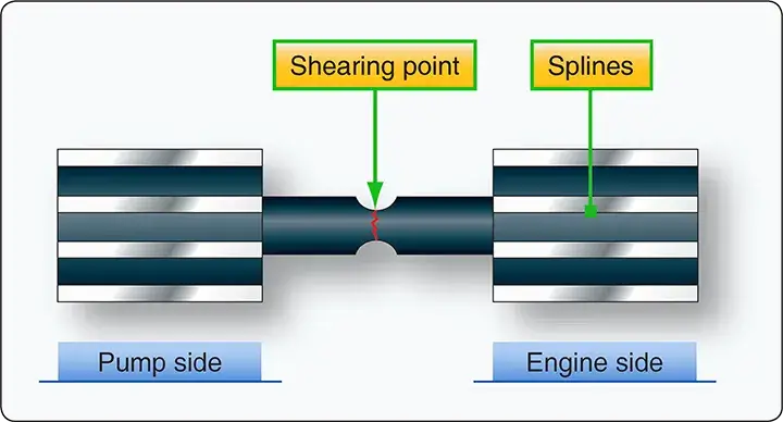 |
| Figure 7. Hydraulic pump shear shaft |
The basic pumping mechanism of piston-type pumps consists of a multiple-bore cylinder block, a piston for each bore, and a valve plate with inlet and outlet slots. The purpose of the valve plate slots is to let fluid into and out of the bores as the pump operates. The cylinder bores lie parallel to and symmetrically around the pump axis. All aircraft axial-piston pumps have an odd number of pistons. [Figure 8]
 |
| Figure 8. Axial inline piston pump |
Bent Axis Piston Pump
A typical constant-displacement axial-type pump is shown in Figure 9. The angular housing of the pump causes a corresponding angle to exist between the cylinder block and the drive shaft plate to which the pistons are attached. It is this angular configuration of the pump that causes the pistons to stroke as the pump shaft is turned.
 |
| Figure 9. Bent axis piston pump |
When the pump operates, all parts within the pump (except the outer races of the bearings that support the drive shaft, the cylinder bearing pin on which the cylinder block turns, and the oil seal) turn together as a rotating group. At one point of rotation of the rotating group, a minimum distance exists between the top of the cylinder block and the upper face of the drive shaft plate. Because of the angled housing at a point of rotation 180° away, the distance between the top of the cylinder block and the upper face of the drive shaft plate is at a maximum.
At any given moment of operation, three of the pistons are moving away from the top face of the cylinder block, producing a partial vacuum in the bores in which these pistons operate. This occurs over the inlet port, so fluid is drawn into these bores at this time. On the opposite side of the cylinder block, three different pistons are moving toward the top face of the block. This occurs while the rotating group is passing over the outlet port causing fluid to be expelled from the pump by these pistons. The continuous and rapid action of the pistons is overlapping in nature and results in a practically nonpulsating pump output.
Inline Piston Pump
The simplest type of axial piston pump is the swash plate design in which a cylinder block is turned by the drive shaft. Pistons fitted to bores in the cylinder block are connected through piston shoes and a retracting ring so that the shoes bear against an angled swash plate.
As the block turns, the piston shoes follow the swash plate, causing the pistons to reciprocate. The ports are arranged in the valve plate so that the pistons pass the inlet as they are pulled out, and pass the outlet as they are forced back in. In these pumps, displacement is determined by the size and number of pistons, as well as their stroke length, which varies with the swash plate angle. This constant-displacement pump is illustrated in Figure 8.
Vane Pump
The vane-type power pump is also a constant-displacement pump. It consists of a housing containing four vanes (blades), a hollow steel rotor with slots for the vanes, and a coupling to turn the rotor. [Figure 10]
 |
| Figure 10. Vane-type power pump |
The rotor is positioned off center within the sleeve. The vanes, which are mounted in the slots in the rotor, together with the rotor, divide the bore of the sleeve into four sections. As the rotor turns, each section passes one point where its volume is at a minimum and another point where its volume is at a maximum. The volume gradually increases from minimum to maximum during the first half of a revolution and gradually decreases from maximum to minimum during the second half of the revolution.
As the volume of a given section increases, that section is connected to the pump inlet port through a slot in the sleeve. Since a partial vacuum is produced by the increase in volume of the section, fluid is drawn into the section through the pump inlet port and the slot in the sleeve. As the rotor turns through the second half of the revolution and the volume of the given section is decreasing, fluid is displaced out of the section, through the slot in the sleeve aligned with the outlet port, and out of the pump.
Variable-Displacement Pump
A variable-displacement pump has a fluid output that is varied to meet the pressure demands of the system. The pump output is changed automatically by a pump compensator within the pump. The following paragraph discusses a two-stage Vickers variable displacement pump. The first stage of the pump consists of a centrifugal pump that boosts the pressure before the fluid enters the piston pump. [Figure 11]
 |
| Figure 11. Variable displacement pump |
Basic Pumping Operation
The aircraft’s engine rotates the pump drive shaft, cylinder block, and pistons via a gearbox. Pumping action is generated by piston shoes that are restrained and slide on the shoe bearing plate in the yoke assembly. Because the yoke is at an angle to the drive shaft, the rotary motion of the shaft is converted to piston reciprocating motion.
As the piston begins to withdraw from the cylinder block, system inlet pressure forces fluid through a porting arrangement in the valve plate into the cylinder bore. The piston shoes are restrained in the yoke by a piston shoe retaining plate and a shoe plate during the intake stroke. As the drive shaft continues to turn the cylinder block, the piston shoe continues following the yoke bearing surface. This begins to return the piston into its bore (i.e., toward the valve block).
The fluid contained in the bore is precompressed, then expelled through the outlet port. Discharge pressure holds the piston shoe against the yoke bearing surface during the discharge stroke and also provides the shoe pressure balance and fluid film through an orifice in the piston and shoe subassembly.
With each revolution of the drive shaft and cylinder block, each piston goes through the pumping cycle described above, completing one intake and one discharge stroke. High-pressure fluid is ported out through the valve plate, past the blocking valve, to the pump outlet. The blocking valve is designed to remain open during normal pump operation. Internal leakage keeps the pump housing filled with fluid for lubrication of rotating parts and cooling. The leakage is returned to the system through a case drain port. The case valve relief valve protects the pump against excessive case pressure, relieving it to the pump inlet.
Normal Pumping Mode
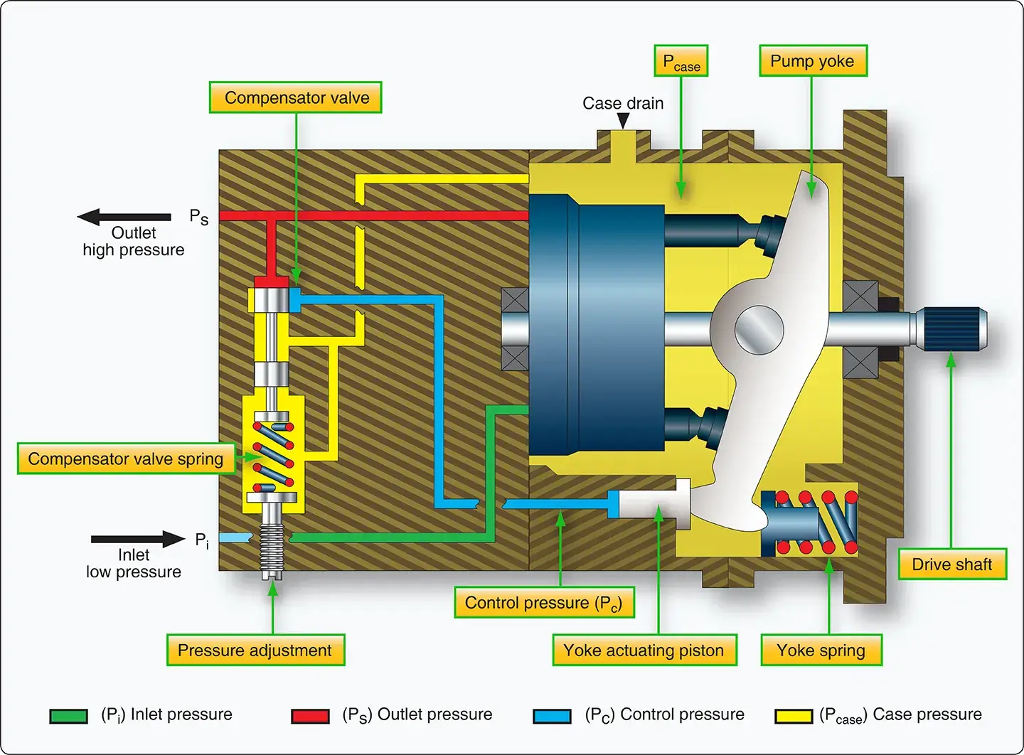
The pressure compensator is a spool valve that is held in the closed position by an adjustable spring load. [Figure 12] When pump outlet pressure (system pressure) exceeds the pressure setting (2,850 psi for full flow), the spool moves to admit fluid from the pump outlet against the yoke actuator piston. In Figure 12, the pressure compensator is shown at cracking pressure; the pump outlet pressure is just high enough to move the spool to begin admitting fluid to the actuator piston.
 |
| Figure 12. Normal pumping mode |
The yoke is supported inside the pump housing on two bearings. At pump outlet pressures below 2,850 psi, the yoke is held at its maximum angle relative to the drive shaft centerline by the force of the yoke return spring. Decreasing system flow demand causes outlet pressure to become high enough to crack the compensator valve open and admit fluid to the actuator piston.
This control pressure overcomes the yoke return spring force and strokes the pump yoke to a reduced angle. The reduced angle of the yoke results in a shorter stroke for the pistons and reduced displacement. [Figure 13]
 |
| Figure 13. Yoke angle |
The lower displacement results in a corresponding reduction in pump flow. The pump delivers only that flow required to maintain the desired pressure in the system. When there is no demand for flow from the system, the yoke angle decreases to nearly zero degrees stroke angle. In this mode, the unit pumps only its own internal leakage. Thus, at pump outlet pressures above 2,850 psi, pump displacement decreases as outlet pressure rises.
At system pressures below this level, no fluid is admitted through the pressure compensator valve to the actuator piston and the pump remains at full displacement, delivering full flow. Pressure is then determined by the system demand. The unit maintains zero flow at system pressure of 3,025 psi.
Depressurized Mode
When the solenoid valve is energized, the EDV solenoid valve moves up against the spring force and the outlet fluid is ported to the EDV control piston on the top of the compensator (depressurizing piston). [Figure 14]
 |
| Figure 14. Depressurized mode |
The high-pressure fluid pushes the compensator spool beyond its normal metering position. This removes the compensator valve from the circuit and connects the actuator piston directly to the pump outlet. Outlet fluid is also ported to the blocking valve spring chamber, which equalizes pressure on both sides of its plunger. The blocking valve closes due to the force of the blocking valve spring and isolates the pump from the external hydraulic system.
The pump strokes itself to zero delivery at an outlet pressure that is equal to the pressure required on the actuator piston to reduce the yoke angle to nearly zero, approximately 1,100 psi. This depressurization and blocking feature can be used to reduce the load on the engine during startup and, in a multiple pump system, to isolate one pump at a time and check for proper system pressure output.