Hydraulic accumulators are used in aircraft hydraulic systems to store hydraulic energy, smooth pressure fluctuations, and provide an emergency source of hydraulic power. By using compressed nitrogen or air to store energy, accumulators help maintain steady system pressure and improve the performance of hydraulic components during periods of high demand or temporary pump failure.
The accumulator is a steel sphere divided into two chambers by a synthetic rubber diaphragm. The upper chamber contains fluid at system pressure, while the lower chamber is charged with nitrogen or air. Cylindrical types are also used in high-pressure hydraulic systems. Many aircraft have several accumulators in the hydraulic system. There may be a main system accumulator and an emergency system accumulator. There may also be auxiliary accumulators located in various sub-systems.
The function of an accumulator is to:
- Dampen pressure surges in the hydraulic system caused by actuation of a unit and the effort of the pump to maintain pressure at a preset level.
- Aid or supplement the power pump when several units are operating at once by supplying extra power from its accumulated, or stored, power.
- Store power for the limited operation of a hydraulic unit when the pump is not operating.
- Supply fluid under pressure to compensate for small internal or external (not desired) leaks that would cause the system to cycle continuously by action of the pressure switches continually kicking in.
Types of Accumulators
There are two general types of accumulators used in aircraft hydraulic systems: spherical and cylindrical.
Spherical Accumulator
The spherical-type accumulator is constructed in two halves that are fastened and threaded, or welded, together. Two threaded openings exist. The top port accepts fittings to connect to the pressurized hydraulic system to the accumulator. The bottom port is fitted with a gas servicing valve, such as a Schrader valve. A synthetic rubber diaphragm, or bladder, is installed in the sphere to create two chambers. Pressurized hydraulic fluid occupies the upper chamber and nitrogen or air charges the lower chamber. A screen at the fluid pressure port keeps the diaphragm, or bladder, from extruding through the port when the lower chamber is charged and hydraulic fluid pressure is zero. A rigid button or disc may also be attached to the diaphragm, or bladder, for this purpose. [Figure 1] The bladder is installed through a large opening in the bottom of the sphere and is secured with a threaded retainer plug. The gas servicing valve mounts into the retainer plug.
 |
| Figure 1. A spherical accumulator with diaphragm (left) and bladder (right) |
Cylindrical Accumulator
Cylindrical accumulators consist of a cylinder and piston assembly. End caps are attached to both ends of the cylinder. The internal piston separates the fluid and air/nitrogen chambers. The end caps and piston are sealed with gaskets and packings to prevent external leakage around the end caps and internal leakage between the chambers. In one end cap, a hydraulic fitting is used to attach the fluid chamber to the hydraulic system. In the other end cap, a filler valve is installed to perform the same function as the filler valve installed in the spherical accumulator. [Figure 2]
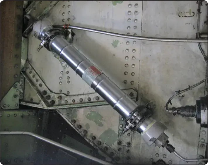 |
| Figure 2. Cylindrical accumulator |
Accumulator Operation
In operation, the compressed-air chamber is charged to a predetermined pressure that is somewhat lower than the system operating pressure. This initial charge is referred to as the accumulator preload. As an example of accumulator operation, let us assume that the cylindrical accumulator is designed for a preload of 1,300 psi in a 3,000-psi system.
When the initial charge of 1,300 psi is introduced into the unit, hydraulic system pressure is zero. As air pressure is applied through a gas servicing valve, it moves the piston toward the opposite end until it bottoms. If the air behind the piston has a pressure of 1,300 psi, the hydraulic system pump has to create a pressure within the system greater than 1,300 psi before the hydraulic fluid can actuate the piston. At 1,301 psi the piston starts to move within the cylinder, compressing the air as it moves. At 2,000 psi, it has backed up several inches. At 3,000 psi, the piston has backed up to its normal operating position, compressing the air until it occupies a space less than one-half the length of the cylinder. When actuation of hydraulic units lowers the system pressure, the compressed air expands against the piston, forcing fluid from the accumulator. This supplies an instantaneous supply of fluid to the hydraulic system component. The charged accumulator may also supply fluid pressure to actuate a component(s) briefly in case of pump failure.
Maintenance of Accumulators
Maintenance consists of inspections, minor repairs, replacement of component parts, and testing. There is an element of danger in maintaining accumulators. Therefore, proper precautions must be strictly observed to prevent injury and damage.
Before disassembling any accumulator, ensure that all preload air (or nitrogen) pressure has been discharged. Failure to release the preload could result in serious injury to the technician. Before making this check, be certain you know the type of high-pressure air valve used. When you know that all air pressure has been removed, you can take the unit apart. Be sure to follow manufacturer’s instructions for the specific unit you have.