 |
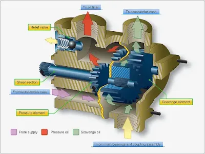
| Figure 2. Cutaway view of gear oil pump |
The gear-type oil pump has only two elements: one for pressure oil and one for scavenging. [Figure 2] However, some types of pumps may have several elements: one or more elements for pressure and two or more for scavenging. The clearances between the gear teeth and the sides of the pump wall and plate are critical to maintain the correct output of the pump.
A regulating (relief) valve in the discharge side of the pump limits the output pressure of the pump by bypassing oil to the pump inlet when the outlet pressure exceeds a predetermined limit. [Figure 2] The regulating valve can be adjusted, if needed, to bring the oil pressure within limits. Also shown is the shaft shear section that causes the shaft to shear if the pump gears should seize up and not turn.
The gerotor pump, like the gear pump, usually contains a single element for oil pressure and several elements for scavenging oil. Each of the elements, pressure and scavenge, is almost identical in shape; however, the capacity of the elements can be controlled by varying the size of the gerotor elements. For example, the pressure element may have a pumping capacity of 3.1 gallon per minute (gpm) as compared to 4.25 gpm capacity for the scavenge elements. Consequently, the pressure element is smaller since the elements are all driven by a common shaft. The pressure is determined by engine rpm with a minimum pressure at idling speed and maximum pressure at intermediate and maximum engine speeds.
A typical set of gerotor pumping elements is shown in Figure 3. Each set of gerotors is separated by a steel plate, making each set an individual pumping unit consisting of an inner and an outer element. The small star-shaped inner element has external lobes that fit within and are matched with the outer element that has internal lobes. The small element fits on and is keyed to the pump shaft and acts as a drive for the outer free-turning element. The outer element fits within a steel plate having an eccentric bore. In one engine model, the oil pump has four elements: one for oil feed and three for scavenge. In some other models, pumps have six elements: one for feed and five for scavenge. In each case, the oil flows as long as the engine shaft is turning.
 |
| Figure 3. Typical gerotor pumping elements |
Turbine Oil Filters
Filters are an important part of the lubrication system because they remove foreign particles that may be in the oil. This is particularly important in gas turbines as very high engine speeds are attained; the antifriction types of ball and roller bearings would become damaged quite rapidly if lubricated with contaminated oil. Also, there are usually numerous drilled or core passages leading to various points of lubrication. Since these passages are usually rather small, they are easily clogged.
There are several types and locations of filters used for filtering the turbine lubricating oil. The filtering elements come in a variety of configurations and mesh sizes. Mesh sizes are measured in microns, which is a linear measurement equal to one millionth of a meter (a very small opening).
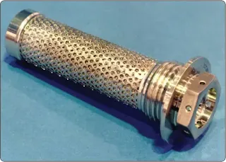
A main oil strainer filter element is shown in Figure 4. The filtering element interior is made of varying materials including paper and metal mesh. [Figure 5] Oil normally flows through the filter element from the outside into the filter body. One type of oil filter uses a replaceable laminated paper element, while others use a very fine stainless steel metal mesh of about 25–35 microns.
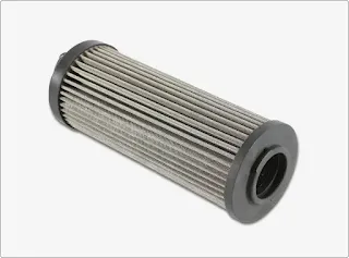 |
| Figure 4. Turbine oil filter element |
 |
| Figure 5. Turbine oil filter paper element |
Most filters are located close to the pressure pump and consist of a filter body or housing, filter element, a bypass valve, and a check valve. The filter bypass valve prevents the oil flow from being stopped if the filter element becomes clogged. The bypass valve opens whenever a certain pressure is reached. If this occurs, the filtering action is lost, allowing unfiltered oil to be pumped to the bearings. However, this prevents the bearings from receiving no oil at all. In the bypass mode, many engines have a mechanical indicator that pops out to indicate the filter is in the bypass mode. This indication is visual and can only be seen by inspecting the engine directly. An antidrain check valve is incorporated into the assembly to prevent the oil in the tank from draining down into the engine sumps when the engine is not operating. This check valve is normally spring loaded closed with 4 to 6 psi needed to open it.
The filters generally discussed are used as main oil filters; that is, they strain the oil as it leaves the pump before being piped to the various points of lubrication. In addition to the main oil filters, there are also secondary filters located throughout the system for various purposes. For instance, there may be a finger screen filter that is sometimes used for straining cavenged oil. These screens tend to be large mesh screens that trap larger contaminants. Also, there are fine-mesh screens called last chance filters for straining the oil just before it passes from the spray nozzles onto the bearing surfaces. [Figure 6] These filters are located at each bearing and help screen out contaminants that could plug the oil spray nozzle.
 |
| Figure 6. Last-chance filter before spray nozzle |
Oil Pressure Regulating Valve
Most turbine engine oil systems are the pressure regulating type system that keeps the pressure fairly constant. An oil pressure regulating valve is included in the oil system on the pressure side of the pressure pump. A regulating valve system controls the systems pressure to a limited pressure within the system. It is more of a regulating valve than a relief valve because it keeps the pressure in the system within certain limits other than only opening when the absolute maximum pressure of the system is exceeded.
The regulating valve Figure 7 has a valve held against a seat by a spring. By adjusting the tension (increase) on the spring, you change the pressure at which the valve opens and you also increase the system pressure. A screw pressing on the spring adjusts the tension on the valve and the system pressure.
 |
| Figure 7. Pressure regulating valve |
Oil Pressure Relief Valve
Some large turbofan oil systems do not have a regulating valve. The system pressure varies with engine rpm and pump speed. There is a wide range of pressure in this system. A relief valve is used to relieve pressure only if it exceeds the maximum limit for the system. [Figure 8] This true relief valve system is preset to relieve pressure and bypass the oil back to the inlet side of the oil pump whenever the pressure exceeds the maximum preset system limit. This relief valve is especially important when oil coolers are incorporated in the system since the coolers are easily ruptured because of their thin-wall construction. Under normal operation, it should never open.
 |
| Figure 8. Pressure relief valve |
Oil Jets
Oil jets (or nozzles) are located in the pressure lines adjacent to, or within, the bearing compartments and rotor shaft couplings. [Figure 9] The oil from these nozzles is delivered in the form of an atomized spray. Some engines use an air-oil mist spray that is produced by tapping high-pressure bleed air from the compressor to the oil nozzle outlet. This method is considered adequate for ball and roller bearings; however, the solid oil spray method is considered the better of the two methods. The oil jets are easily clogged because of the small orifice in their tips; consequently, the oil must be free of any foreign particles. If the last-chance filters in the oil jets should become clogged, bearing failure usually results since nozzles are not accessible for cleaning except during engine maintenance. To prevent damage from clogged oil jets, main oil filters are checked frequently for contamination.
 |
| Figure 9. Oil nozzles spray lubricate on bearings |
Lubrication System Instrumentation
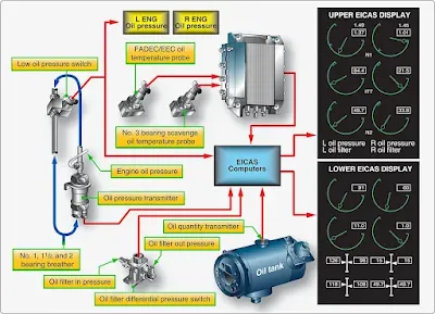
Gauge connection provisions are incorporated in the oil system for oil pressure, oil quantity, low oil pressure, oil filter differential pressure switch, and oil temperature. The oil pressure gauge measures the pressure of the lubricant as it leaves the pump and enters the pressure system. The oil pressure transmitter connection is located in the pressure line between the pump and the various points of lubrication. An electronic sensor is placed to send a signal to the Full Authority Digital Engine Control (FADEC) control unit and through the Engine Indicating and Crew Alerting System (EICAS) computers, and on to the displays in the flight deck. [Figure 10] The tank quantity transmitter information is sent to the EICAS computers. The low oil pressure switch alerts the crew if the oil pressure falls below a certain pressure during engine operation. The differential oil pressure switch alerts the flight crew of an impending oil filter bypass because of a clogged filter. A message is sent to the display in the upper EICAS display in the flight deck as can be seen in Figure 10. Oil temperature can be sensed at one or more points in the engine’s oil flow path. The signal is sent to the FADEC/EICAS computer and is displayed on the lower EICAS display.
 |
| Figure 10. Oil indicating system |
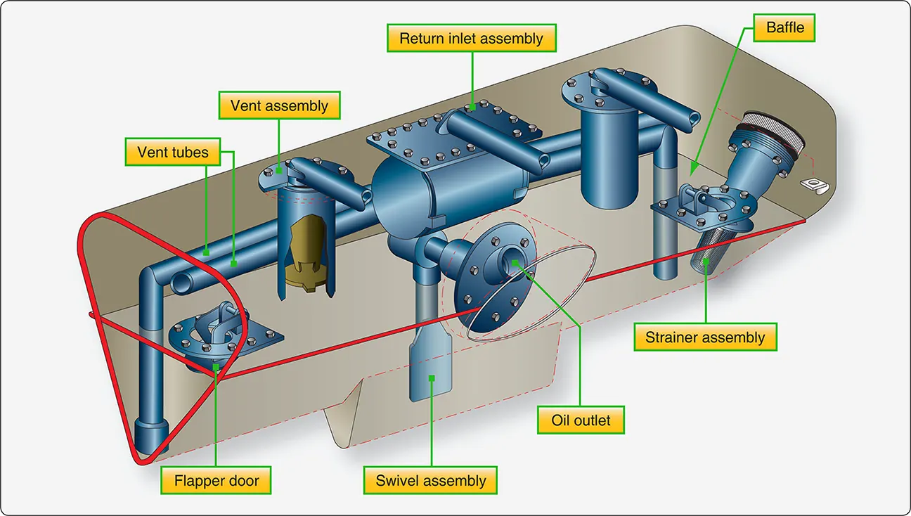
Lubrication System Breather Systems (Vents)
Breather subsystems are used to remove excess air from the bearing cavities and return the air to the oil tank where it is separated from any oil mixed in the vapor of air and oil by the deaerator. Then, the air is vented overboard and back to the atmosphere. All engine bearing compartments, oil tanks, and accessory cases are vented together so the pressure in the system remains the same.
The vent in an oil tank keeps the pressure within the tank from rising above or falling below that of the outside atmosphere. However, the vent may be routed through a check relief valve that is preset to maintain a slight (approximately 4 psi) pressure on the oil to assure a positive flow to the oil pump inlet.
In the accessory case, the vent (or breather) is a screen-protected opening that allows accumulated air pressure within the accessory case to escape to the atmosphere. The scavenged oil carries air into the accessory case and this air must be vented. Otherwise, the pressure buildup within the accessory case would stop the flow of oil draining from the bearing, forcing this oil past the bearing oil seals and into the compressor housing. If in enough quantity, oil leakage could cause burning and seal and bearing malfunction. The screened breathers are usually located in the front center of the accessory case to prevent oil leakage through the breather when the aircraft is in unusual flight attitudes. Some breathers may have a baffle to prevent oil leakage during flight maneuvers. A vent that leads directly to the bearing compartment may be used in some engines. This vent equalizes pressure around the bearing surface so that the lower pressure at the first compressor stage does not cause oil to be forced past the bearing rear oil seal into the compressor.
Lubrication System Check Valve
Check valves are sometimes installed in the oil supply lines of dry- sump oil systems to prevent reservoir oil from seeping (by gravity) through the oil pump elements and high-pressure lines into the engine after shutdown. Check valves, by stopping flow in an opposite direction, prevent accumulations of undue amounts of oil in the accessory gearbox, compressor rear housing, and combustion chamber. Such accumulations could cause excessive loading of the accessory drive gears during starts, contamination of the cabin pressurization air, or internal oil fires. The check valves are usually the spring-loaded ball-and-socket type constructed for free flow of pressure oil. The pressure required to open these valves varies, but the valves generally require from 2 to 5 psi to permit oil to flow to the bearings.
Lubrication System Thermostatic Bypass Valves
Thermostatic bypass valves are included in oil systems using an oil cooler. Although these valves may be called different names, their purpose is always to maintain proper oil temperature by varying the proportion of the total oil flow passing through the oil cooler. A cutaway view of a typical thermostatic bypass valve is shown in Figure 11. This valve consists of a valve body, having two inlet ports and one outlet port, and a spring-loaded thermostatic element valve. The valve is spring loaded because the pressure drop through the oil cooler could become too great due to denting or clogging of the cooler tubing. In such a case, the valve opens, bypassing the oil around the cooler.
 |
| Figure 11. Typical thermostatic bypass valve |
Air Oil Coolers
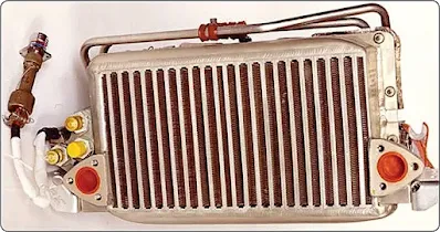
Two basic types of oil coolers in general use are the air-cooled and the fuel-cooled. Air oil coolers are used in the lubricating systems of some turbine engines to reduce the temperature of the oil to a degree suitable for recirculation through the system. The air-cooled oil cooler is normally installed at the forward end of the engine. It is similar in construction and operation to the air-cooled cooler used on reciprocating engines. An air oil cooler is usually included in a dry-sump oil system. [Figure 12] This cooler may be air-cooled or fuel-cooled and many engines use both. Dry- sump lubrication systems require coolers for several reasons. First, air cooling of bearings by using compressor bleed-air is not sufficient to cool the turbine bearing cavities because of the heat present in area of the turbine bearings. Second, the large turbofan engines normally require a greater number of bearings, which means that more heat is transferred to the oil. Consequently, the oil coolers are the only means of dissipating the oil heat.
 |
| Figure 12. Air oil cooler |
Fuel Oil Coolers
The fuel-cooled oil cooler acts as a fuel oil heat exchanger in that the fuel cools the hot oil and the oil heats the fuel for combustion. [Figure 13] Fuel flowing to the engine must pass through the heat exchanger; however, there is a thermostatic valve that controls the oil flow, and the oil may bypass the cooler if no cooling is needed. The fuel/oil heat exchanger consists of a series of joined tubes with an inlet and outlet port. The oil enters the inlet port, moves around the fuel tubes, and goes out the oil outlet port.
The deoiler removes the oil from the breather air. The breather air goes into an impeller that turns in the deoiler housing. Centrifugal force drives the oil towards the outer wall of the impeller. Then, the oil drains from the deoiler into a sump or oil tank. Because the air is much lighter than the oil, it goes through the center of the impeller and is vented overboard.
Magnetic chip detectors are used in the oil system to detect and catch ferrous (magnetic) particles present in the oil. [Figure 14] Scavenge oil generally flows past chip detectors so any magnetic particles are attracted and stick to the chip detector. Chip detectors are placed in several locations but generally are in the scavenge lines for each scavenge pump, oil tank, and in the oil sumps. Some engines have several detectors to one detector. During maintenance, the chip detectors are removed from the engine and inspected for metal; if none is found, the detector is cleaned, replaced, and safety wired. If metal is found on a chip detector, an investigation should be made to find the source of the metal on the chip.