Without modern metalworking tools and machines, the job of the airframe technician would be more difficult and tiresome, and the time required to finish a task would be much greater. These specialized tools and machines help the airframe technician construct or repair sheet metal in a faster, simpler, and better manner than possible in the past. Powered by human muscle, electricity, or compressed air, these tools are used to lay out, mark, cut, sand, or drill sheet metal.
Layout Tools
Before fitting repair parts into an aircraft structure, the new sections must be measured and marked, or laid out to the dimensions needed to make the repair part. Tools utilized for this process are discussed in this section.
Scales
Scales are available in various lengths, with the 6-inch and 12-inch scales being the most common and affordable. A scale with fractions on one side and decimals on the other side is very useful. To obtain an accurate measurement, measure with the scale held on edge from the 1-inch mark instead of the end. Use the graduation marks on the side to set a divider or compass. [Figure 1]
 |
| Figure 1. Scales |
Combination Square
A combination square consists of a steel scale with three heads that can be moved to any position on the scale and locked in place. The three heads are a stock head that measures 90° and 45° angles, a protractor head that can measure any angle between the head and the blade, and a center head that uses one side of the blade as the bisector of a 90° angle. The center of a shaft can be found by using the center head. Place the end of the shaft in the V of the head and scribe a line along the edge of the scale. Rotate the head about 90° and scribe another line along the edge of the scale. The two lines will cross at the center of the shaft. [Figure 2]
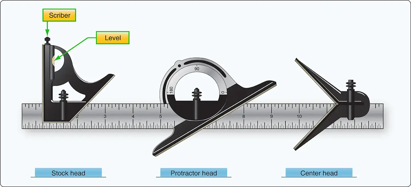 |
| Figure 2. Combination square |
Dividers
Dividers are used to transfer a measurement from a device to a scale to determine its value. Place the sharp points at the locations from which the measurement is to be taken. Then, place the points on a steel machinist’s scale, but put one of the points on the 1-inch mark and measure from there. [Figure 3]
 |
| Figure 3. Divider |
Rivet Spacers
A rivet spacer is used to make a quick and accurate rivet pattern layout on a sheet. On the rivet spacer, there are alignment marks for 1⁄2-inch, 3⁄4-inch, 1-inch and 2-inch rivet spacing. [Figure 4]
 |
| Figure 4. Rivet spacer |
Marking Tools
Fiber-tipped Pens
Fiber-tipped pens are the preferred method of marking lines and hole locations directly on aluminum, because the graphite in a No. 2 pencil can cause corrosion when used on aluminum. Make the layout on the protective membrane if it is still on the material, or mark directly on the material with a fiber-tipped pen, such as a fine-point Sharpie®, or cover the material with masking tape and then mark on the tape.
Scribes
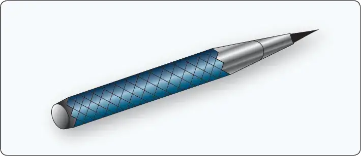
A scribe is a pointed instrument used to mark or score metal to show where it is to be cut. A scribe should only be used when marks will be removed by drilling or cutting because it makes scratches that weaken the material and could cause corrosion. [Figure 5]
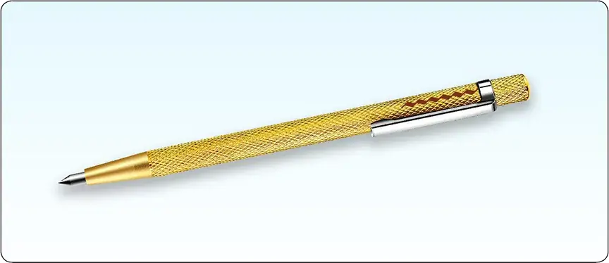 |
| Figure 5. Scribe |
Punches
Punches are usually made of carbon steel that has been hardened and tempered. Generally classified as solid or hollow, punches are designed according to their intended use. A solid punch is a steel rod with various shapes at the end for different uses. For example, it is used to drive bolts out of holes, loosen frozen or tight pins and keys, knock out rivets, pierce holes in a material, etc. The hollow punch is sharp edged and used most often for cutting out blanks. Solid punches vary in both size and point design, while hollow punches vary in size.
Prick Punch
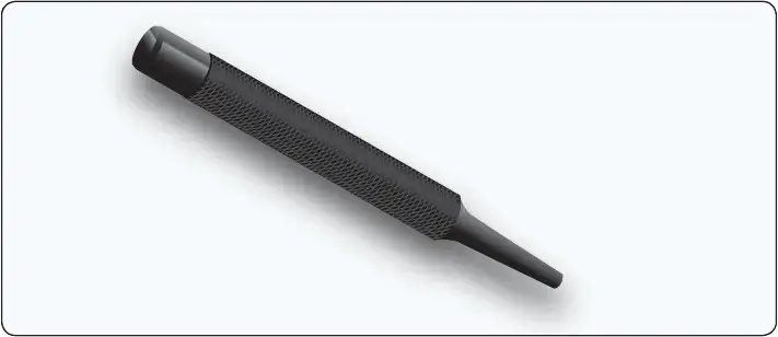
A prick punch is primarily used during layout to place reference marks on metal because it produces a small indentation. [Figure 6] After layout is finished, the indentation is enlarged with a center punch to allow for drilling. The prick punch can also be used to transfer dimensions from a paper pattern directly onto the metal. Take the following precautions when using a prick punch:
- Never strike a prick punch a heavy blow with a hammer because it could bend the punch or cause excessive damage to the item being worked.
- Do not use a prick punch to remove objects from holes because the point of the punch spreads the object and causes it to bind even more.
 |
| Figure 6. Prick punch |
Center Punch
A center punch is used to make indentations in metal as an aid in drilling. [Figure 7] These indentations help the drill, which has a tendency to wander on a flat surface, stay on the mark as it goes through the metal. The traditional center punch is used with a hammer, has a heavier body than the prick punch, and has a point ground to an angle of about 60°. Take the following precautions when using a center punch;
- Never strike the center punch with enough force to dimple the item around the indentation or cause the metal to protrude through the other side of the sheet.
- Do not use a center punch to remove objects from holes because the point of the punch spreads the object and causes it to bind even more.
 |
| Figure 7. Center punch |
Automatic Center Punch
The automatic center punch performs the same function as an ordinary center punch, but uses a spring tension mechanism to create a force hard enough to make an indentation without the need for a hammer. The mechanism automatically strikes a blow of the required force when placed where needed and pressed. This punch has an adjustable cap for regulating the stroke; the point can be removed for replacement or sharpening. Never strike an automatic center punch with a hammer. [Figure 8]
 |
| Figure 8. Automatic center punch |
Transfer Punch
A transfer punch uses a template or existing holes in the structure to mark the locations of new holes. The punch is centered in the old hole over the new sheet and lightly tapped with a mallet. The result should be a mark that serves to locate the hole in the new sheet. [Figure 9]
 |
| Figure 9. Transfer punch |
Drive Punch
The drive punch is made with a flat face instead of a point because it is used to drive out damaged rivets, pins, and bolts that sometimes bind in holes. The size of the punch is determined by the width of the face, usually 1⁄8-inch to 1⁄4-inch. [Figure 10]
 |
| Figure 10. Drive punch |
Pin Punch
The pin punch typically has a straight shank characterized by a hexagonal body. Pin punch points are sized in 1⁄32-inch increments of an inch and range from 1⁄16-inch to 3⁄8-inch in diameter. The usual method for driving out a pin or bolt is to start working it out with a drive punch until the shank of the punch is touching the sides of the hole. Then use a pin punch to drive the pin or bolt the rest of the way out of the hole. [Figure 11]
 |
| Figure 11. Pin punch |
Chassis Punch
A chassis punch is used to make holes in sheet metal parts for the installation of instruments and other avionics appliance, as well as lightening holes in ribs and spars. Sized in 1⁄16 of an inch, they are available in sizes from 1⁄2 inch to 3 inches. [Figure 12]
 |
| Figure 12. Chassis punch |
Awl
A pointed tool for marking surfaces or for punching small holes, an awl is used in aircraft maintenance to place scribe marks on metal and plastic surfaces and to align holes, such as in the installation of a deicer boot. [Figure 13]
 |
| Figure 13. Awl |
Procedures for one use of an awl:
- Place the metal to be scribed on a flat surface. Place a ruler or straightedge on the guide marks already measured and placed on the metal.
- Remove the protective cover from the awl.
- Hold the straightedge firmly. Hold the awl, as shown in Figure 14, and scribe a line along the straightedge.
- Replace the protective cover on the awl.
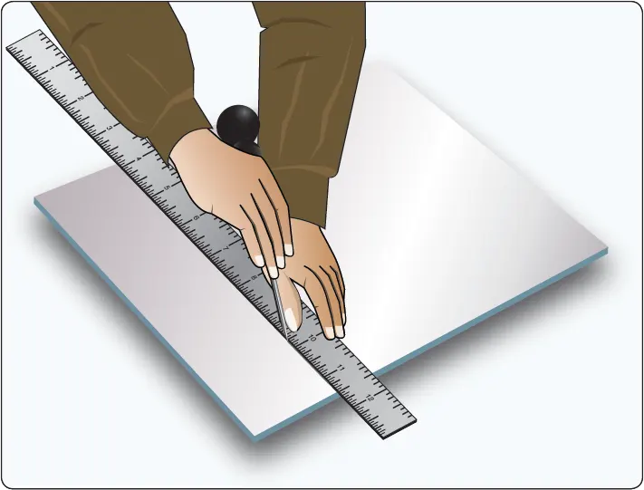 |
| Figure 14. Awl usage |
Hole Duplicator
Available in a variety of sizes and styles, hole duplicators, or hole finders, utilize the old covering as a template to locate and match existing holes in the structure. Holes in a replacement sheet or in a patch must be drilled to match existing holes in the structure and the hole duplicator simplifies this process.
Figure 15 illustrates one type of hole duplicator. The peg on the bottom leg of the duplicator fits into the existing rivet hole. To make the hole in the replacement sheet or patch, drill through the bushing on the top leg. If the duplicator is properly made, holes drilled in this manner are in perfect alignment. A separate duplicator must be used for each diameter of rivet.
 |
| Figure 15. Hole duplicator |
Cutting Tools
Powered and nonpowered metal cutting tools available to the aviation technician include various types of saws, nibblers, shears, sanders, notchers, and grinders.
Circular-Cutting Saws
The circular cutting saw cuts with a toothed, steel disk that rotates at high speed. Handheld or table mounted and powered by compressed air, this power saw cuts metal or wood. To prevent the saw from grabbing the metal, keep a firm grip on the saw handle at all times. Check the blade carefully for cracks prior to installation because a cracked blade can fly apart during use, possibly causing serious injury.
Kett Saw
The Kett saw is an electrically operated, portable circular cutting saw that uses blades of various diameters. [Figure 16] Since the head of this saw can be turned to any desired angle, it is useful for removing damaged sections on a stringer.
 |
| Figure 16. Kett saw |
The advantages of a Kett saw include:
- Can cut metal up to 3⁄16-inch in thickness.
- No starting hole is required.
- A cut can be started anywhere on a sheet of metal.
- Can cut an inside or outside radius.
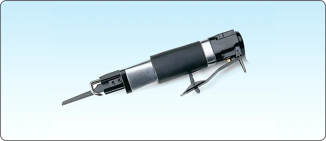
Pneumatic Circular Cutting Saw
The pneumatic circular cutting saw, useful for cutting out damage, is similar to the Kett saw. [Figure 17]
 |
| Figure 17. Pneumatic circular saw |
Reciprocating Saw
The versatile reciprocating saw achieves cutting action through a push and pull (reciprocating) motion of the blade. This saw can be used right sideup or upside down, a feature that makes it handier than the circular saw for working in tight or awkward spots. A variety of blade types are available for reciprocating saws; blades with finer teeth are used for cutting through metal.
The portable, air-powered reciprocating saw uses a standard hacksaw blade and can cut a 360° circle or a square or rectangular hole. Unsuited for fine precision work, this saw is more difficult to control than the pneumatic circular cutting saw. A reciprocating saw should be used in such a way that at least two teeth of the saw blade are cutting at all times. Avoid applying too much downward pressure on the saw handle because the blade may break. [Figure 18]
 |
| Figure 18. Reciprocating saw |
Cut-off Wheel
A cut-off wheel is a thin abrasive disc driven by a high-speed pneumatic die-grinder and used to cut out damage on aircraft skin and stringers. The wheels come in different thicknesses and sizes. [Figure 19]
 |
| Figure 19. Die grinder and cut-off wheel |
Nibblers
Usually powered by compressed air, the nibbler is another tool for cutting sheet metal. Portable nibblers utilize a high speed blanking action (the lower die moves up and down and meets the upper stationary die) to cut the metal. [Figure 20] The shape of the lower die cuts out small pieces of metal approximately 1⁄16 inch wide.
 |
| Figure 20. Nibbler |
Shop Tools
Due to size, weight, and/or power source, shop tools are usually in a fixed location, and the airframe part to be constructed or repaired is brought to the tool.
Squaring Shear
The squaring shear provides the airframe technician with a convenient means of cutting and squaring sheet metal. Available as a manual, hydraulic, or pneumatic model, this shear consists of a stationary lower blade attached to a bed and a movable upper blade attached to a crosshead. [Figure 21]
 |
| Figure 21. Power squaring shear |
Two squaring fences, consisting of thick strips of metal used for squaring metal sheets, are placed on the bed. One squaring fence is placed on the right side and one on the left to form a 90° angle with the blades. A scale graduated in fractions of an inch is scribed on the bed for ease in placement.
To make a cut with a foot shear, move the upper blade down by placing the foot on the treadle and pushing downward. Once the metal is cut and foot pressure removed, a spring raises the blade and treadle. Hydraulic or pneumatic models utilize remote foot pedals to ensure operator safety.
The squaring shear performs three distinctly different operations:
- Cutting to a line
- Squaring
- Multiple cutting to a specific size
When cutting to a line, place the sheet on the bed of the shears in front of the cutting blade with the cutting line even with the cutting edge of the bed. To cut the sheet with a foot shear, step on the treadle while holding the sheet securely in place.
Squaring requires several steps. First, one end of the sheet is squared with an edge (the squaring fence is usually used on the edge). Then, the remaining edges are squared by holding one squared end of the sheet against the squaring fence and making the cut, one edge at a time, until all edges have been squared.
When several pieces must be cut to the same dimensions, use the backstop, located on the back of the cutting edge on most squaring shears. The supporting rods are graduated in fractions of an inch and the gauge bar may be set at any point on the rods. Set the gauge bar the desired distance from the cutting blade of the shears and push each piece to be cut against the gauge bar. All the pieces can then be cut to the same dimensions without measuring and marking each one separately.
Foot-operated shears have a maximum metal cutting capacity of 0.063 inch of aluminum alloy. Use powered squaring shears for cutting thicker metals. [Figure 22]
 |
| Figure 22. Foot-operated squaring shear |
Throatless Shear
Airframe technicians use the throatless shear to cut aluminum sheets up to 0.063 inches. This shear takes its name from the fact that metal can be freely moved around the cutting blade during cutting because the shear lacks a “throat” down which metal must be fed. [Figure 23] This feature allows great flexibility in what shapes can be cut because the metal can be turned to any angle for straight, curved, and irregular cuts. Also, a sheet of any length can be cut.
 |
| Figure 23. Throatless shears |
A hand lever operates the cutting blade which is the top blade. Throatless shears made by the Beverly Shear Manufacturing Corporation, called BeverlyTM shears, are often used.
Scroll Shears
Scroll shears are used for cutting irregular lines on the inside of a sheet without cutting through to the edge. [Figure 24] The upper cutting blade is stationary while the lower blade is movable. A handle connected to the lower blade operates the machine.
 |
| Figure 24. Scroll shears |
Rotary Punch Press
Used in the airframe repair shop to punch holes in metal parts, the rotary punch can cut radii in corners, make washers, and perform many other jobs where holes are required. [Figure 25]
 |
| Figure 25. Rotary punch press |
The machine is composed of two cylindrical turrets, one mounted over the other and supported by the frame, with both turrets synchronized to rotate together. Index pins, which ensure correct alignment at all times, may be released from their locking position by rotating a lever on the right side of the machine. This action withdraws the index pins from the tapered holes and allows an operator to turn the turrets to any size punch desired.
When rotating the turret to change punches, release the index lever when the desired die is within 1 inch of the ram, and continue to rotate the turret slowly until the top of the punch holder slides into the grooved end of the ram. The tapered index locking pins will then seat themselves in the holes provided and, at the same time, release the mechanical locking device, which prevents punching until the turrets are aligned. To operate the machine, place the metal to be worked between the die and punch. Pull the lever on the top of the machine toward the operator, actuating the pinion shaft, gear segment, toggle link, and the ram, forcing the punch through the metal. When the lever is returned to its original position, the metal is removed from the punch.
The diameter of the punch is stamped on the front of each die holder. Each punch has a point in its center that is placed in the center punch mark to punch the hole in the correct location.
Band Saw
A band saw consists of a toothed metal band coupled to, and continuously driven around, the circumferences of two wheels. It is used to cut aluminum, steel, and composite parts. [Figure 26] The speed of the band saw and the type and style of the blade depends on the material to be cut. Band saws are often designated to cut one type of material, and if a different material is to be cut, the blade is changed. The speed is controllable and the cutting platform can be tilted to cut angled pieces.
 |
| Figure 26. Band saw |
Disk Sander
Disk sanders have a powered abrasive-covered disk or belt and are used for smoothing or polishing surfaces. The sander unit uses abrasive paper of different grits to trim metal parts. It is much quicker to use a disk sander than to file a part to the correct dimension. The combination disk and belt sander has a vertical belt sander coupled with a disk sander and is often used in a metal shop. [Figure 27]
 |
| Figure 27. Combination disk and belt sander |
Belt Sander
The belt sander uses an endless abrasive belt driven by an electric motor to sand down metal parts much like the disk sander unit. The abrasive paper used on the belt comes in different degrees of grit or coarseness. The belt sander is available as a vertical or horizontal unit. The tension and tracking of the abrasive belt can be adjusted so the belt runs in the middle. [Figure 28]
 |
| Figure 28. Belt sander |
Notcher
The notcher is used to cut out metal parts, with some machines capable of shearing, squaring, and trimming metal. [Figure 29] The notcher consists of a top and bottom die and most often cuts at a 90° angle, although some machines can cut metal into angles up to 180°. Notchers are available in manual and pneumatic models able to cut various thicknesses of mild steel and aluminum. This is an excellent tool for quickly removing corners from sheet metal parts. [Figure 30]
 |
| Figure 29. Notcher |
 |
| Figure 30. Power notcher |
Wet or Dry Grinder
Grinding machines come in a variety of types and sizes, depending upon the class of work for which they are to be used. Dry and/or wet grinders are found in airframe repair shops. Grinders can be bench or pedestal mounted.\
A dry grinder usually has a grinding wheel on each end of a shaft that runs through an electric motor or a pulley operated by a belt.
The wet grinder has a pump to supply a flow of water on a single grinding wheel. The water acts as a lubricant for faster grinding while it continuously cools the edge of the metal, reducing the heat produced by material being ground against the wheel. It also washes away any bits of metal or abrasive removed during the grinding operation. The water returns to a tank and can be re-used.
Grinders are used to sharpen knives, tools, and blades as well as grinding steel, metal objects, drill bits, and tools. Figure 31 illustrates a common type bench grinder found in most airframe repair shops. It can be used to dress mushroomed heads on chisels and points on chisels, screwdrivers, and drills, as well as for removing excess metal from work and smoothing metal surfaces.
 |
| Figure 31. Grinder |
The bench grinder is generally equipped with one mediumgrit and one fine-grit abrasive wheel. The medium-grit wheel is usually used for rough grinding where a considerable quantity of material is to be removed or where a smooth finish is unimportant. The fine-grit wheel is used for sharpening tools and grinding to close limits. It removes metal more slowly, gives the work a smooth finish, and does not generate enough heat to anneal the edges of cutting tools.
Before using any type of grinder, ensure that the abrasive wheels are firmly held on the spindles by the flange nuts. An abrasive wheel that comes off or becomes loose could seriously injure the operator in addition to ruining the grinder. A loose tool rest could cause the tool or piece of work to be “grabbed” by the abrasive wheel and cause the operator’s hand to come in contact with the wheel, possibly resulting in severe wounds.
Always wear goggles when using a grinder, even if eyeshields are attached to the grinder. Goggles should fit firmly against the face and nose. This is the only way to protect the eyes from the fine pieces of steel. Goggles that do not fit properly should be exchanged for ones that do fit. Be sure to check the abrasive wheel for cracks before using the grinder. A cracked abrasive wheel is likely to fly apart when turning at high speeds. Never use a grinder unless it is equipped with wheel guards that are firmly in place.
Grinding Wheels
A grinding wheel is made of a bonded abrasive and provides an efficient way to cut, shape, and finish metals. Available in a wide variety of sizes and numerous shapes, grinding wheels are also used to sharpen knives, drill bits, and many other tools, or to clean and prepare surfaces for painting or plating.
Grinding wheels are removable and a polishing or buffing wheel can be substituted for the abrasive wheel. Silicon carbide and aluminum oxide are the kinds of abrasives used in most grinding wheels. Silicon carbide is the cutting agent for grinding hard, brittle material, such as cast iron. It is also used in grinding aluminum, brass, bronze, and copper. Aluminum oxide is the cutting agent for grinding steel and other metals of high tensile strength.
Hand Cutting Tools
Many types of hand cutting tools are available to cut light gauge sheet metal. Four cutting tools commonly found in the air frame repair shop are straight hand snips, aviation snips, files, and burring tools.
Straight Snips
Straight snips, or sheet metal shears, have straight blades with cutting edges sharpened to an 85° angle. [Figure 32]
 |
| Figure 32. Straight snips |
Available in sizes ranging from 6 to 14 inches, they cut aluminum up to 1⁄16 of an inch. Straight snips can be used for straight cutting and large curves, but aviation snips are better for cutting circles or arcs.
Aviation Snips
Aviation snips are used to cut holes, curved parts, round patches, and doublers (a piece of metal placed under a part to make it stiffer) in sheet metal. Aviation snips have colored handles to identify the direction of the cuts: yellow aviation snips cut straight, green aviation snips curve right, and red aviation snips curve left. [Figure 33]
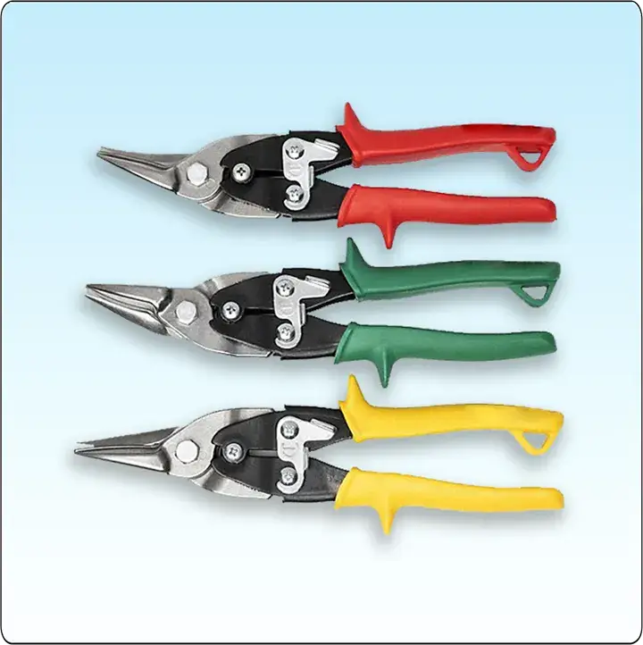 |
| Figure 33. Aviation snips |
Files
The file is an important but often overlooked tool used to shape metal by cutting and abrasion. Files have five distinct properties: length, contour, the form in cross section, the kind of teeth, and the fineness of the teeth. Many different types of files are available and the sizes range from 3 to 18 inches. [Figure 34]
 |
| Figure 34. Files |
The portion of the file on which the teeth are cut is called the face. The tapered end that fits into the handle is called the tang. The part of the file where the tang begins is the heel. The length of a file is the distance from the point or tip to the heel and does not include the tang. The teeth of the file do the cutting. These teeth are set at an angle across the face of the file. A file with a single row of parallel teeth is called a single-cut file. The teeth are cut at an angle of 65°–85° to the centerline, depending on the intended use of the file. Files that have one row of teeth crossing another row in a crisscross pattern are called double-cut files. The angle of the first set usually is 40°–50° and that of the crossing teeth 70°–80°. Crisscrossing produces a surface that has a very large number of little teeth that slant toward the tip of the file. Each little tooth looks like an end of a diamond point cold chisel.
Files are graded according to the tooth spacing; a coarse file has a small number of large teeth, and a smooth file has a large number of fine teeth. The coarser the teeth, the more metal is removed on each stroke of the file. The terms used to indicate the coarseness or fineness of a file are rough, coarse, bastard, second cut, smooth, and dead smooth, and the file may be either single cut or double cut. Files are further classified according to their shape. Some of the more common types are: flat, triangle, square, half round, and round.
There are several filing techniques. The most common is to remove rough edges and slivers from the finished part before it is installed. Crossfiling is a method used for filing the edges of metal parts that must fit tightly together. Crossfiling involves clamping the metal between two strips of wood and filing the edge of the metal down to a preset line. Draw filing is used when larger surfaces need to be smoothed and squared. It is done by drawing the file over the entire surface of the work.
To protect the teeth of a file, files should be stored separately in a plastic wrap or hung by their handles. Files kept in a toolbox should be wrapped in waxed paper to prevent rust from forming on the teeth. File teeth can be cleaned with a file card.
Die Grinder
A die grinder is a handheld tool that turns a mounted cutoff wheel, rotary file, or sanding disk at high speed. [Figure 35] Usually powered by compressed air, electric die grinders are also used. Pneumatic die grinders run at 12,000 to 20,000 revolutions per minute (rpm) with the rotational speed controlled by the operator who uses a handor foot-operated throttle to vary the volume of compressed air. Available in straight, 45°, and 90° models, the die grinder is excellent for weld breaking, smoothing sharp edges, deburring, porting, and general high-speed polishing, grinding, and cutting.
 |
| Figure 35. Die grinder |
Burring Tool
This type of tool is used to remove a burr from an edge of a sheet or to deburr a hole. [Figure 36]
 |
| Figure 36. Burring tools |
RELATED POSTS