Weight and balance in aircraft is based on the law of the lever. This post discusses the application of the law of the lever and its applications relative to locating the balance point of a beam or lever on which various weights are located or shifted. The post also discusses the documentation pertaining to weight and balance that is furnished by the Federal Aviation Administration (FAA) and aircraft manufacturers.
Weight and Balance Theory
Two elements are vital in the weight and balance considerations of an aircraft.- The total weight of the aircraft must be no greater than the maximum weight allowed by the FAA for the make and model of the aircraft.
- The center of gravity (CG), or the point at which all of the weight of the aircraft is considered to be concentrated, must be maintained within the allowable range for the operational weight of the aircraft.
Arm
The arm is usually measured and expressed in inches and refers to the horizontal distance between the CG of an item or object and the datum, a point from where all measurements are taken. Arms to the left of the datum are negative (–) and those to the right of the datum are positive (+). The datum is an imaginary vertical plane from which all horizontal distances are measured for balance purposes. The position of the reference datum varies by aircraft design and manufacturer. When the datum is located off of the lever and to the left, all of the arms are positive and computational errors are minimized. Note: When the datum is established ahead of the aircraft, for example at the aircraft nose, all of the arms are positive and computational errors are minimized.
Moment
A moment is a force that tries to cause rotation and is the product of the arm, in inches, and the weight, in pounds. Moments are generally expressed in pound-inches (lb-in) and may be either positive or negative.
The Law of the Lever
Weight and balance problems are based on the physical law of the lever. This law states that a lever is balanced when the weight on one side of the fulcrum (a pivot point for the lever) multiplied by its arm is equal to the weight on the opposite side multiplied by its arm. In other words, the lever is balanced when the sum of the moments about the fulcrum is zero. This is the condition in which the positive moments (those that try to rotate the lever clockwise) are equal to the negative moments (those that try to rotate it counterclockwise). In an aircraft, the balance point is referred to as the CG.
One of the easiest ways to understand weight and balance is to consider a lever with weights placed at various locations. The balance point or CG of the lever can be changed by either moving the weights closer or farther from the fulcrum or by increasing or decreasing the weights. The balance point or CG of a lever may be determined by using these four steps:
- Measure the arm of each weight in inches from the datum.
- Multiply each arm by its weight in pounds to determine the moment in pound-inches of each weight.
- Determine the total of all weights and of all the moments. (Disregard the weight of the lever).
- Divide the total moment by the total weight to determine the balance point.
Consider these facts about the lever in Figure 1. The 100-pound weight A is located 50 inches to the left of the fulcrum (the datum, in this instance), and it has a moment of 100 × –50 = –5,000 lb-in. The 200-pound weight B is located 25 inches to the right of the fulcrum, and its moment is 200 × +25 = +5,000 lb-in. In Figure 2, the sum of the moments is –5,000 + 5,000 = 0, and the lever is balanced. The forces that try to rotate it clockwise have the same magnitude as those that try to rotate it counterclockwise. If either weight is moved or changed, the balance point or CG changes and the lever becomes unbalanced.
 |
| Figure 1. Balance lever |
 |
| Figure 2. Balance point locations |
In Figure 3, the datum is located off the lever to the left of weight A. Using the information provided in Figure 3, determine the balance point by making a chart like the one in Figure 4.
 |
| Figure 3. Balance lever datum located off the lever |
 |
| Figure 4. Finding balance point with datum located off the lever |
As noted in Figure 4, A weighs 100 pounds and is 50 inches from the datum; B weighs 100 pounds and is 90 inches from the datum; C weighs 200 pounds and is 150 inches from the datum. The total of the weights is 400 pounds, and the total moment is 44,000 lb-in.
Determine the balance point by dividing the total moment by the total weight. A balance point is equal to the CG and can be mathematically written as:
CG = total moment
total weight
To prove this is the correct balance, move the datum to a location 110 inches to the right of the original datum and determine the arm of each weight from this new datum. [Figure 5] Then, make a new chart similar to the one in Figure 6. If the balance point is correct, the sum of the moments is zero.
 |
| Figure 5. Locating balance point |
 |
| Figure 6. Proving balance point with three weights is correct |
The new arm of weight A is 60 inches (the difference between 110 and 50), and since this weight is to the left of the datum, its arm is negative or –60 inches. The new arm of weight B is 20 inches (110 – 90), and it is also to the left of the datum, so it is –20; the new arm of weight C is 40 inches (150 – 110). It is to the right of the datum and is therefore positive.
The lever is balanced when the sum of the moments is zero. The location of the datum used for determining the arms of the weights is not important; it may be in various locations, but all of the measurements must be made from the same datum location.
The procedure for finding the balance point is the same anywhere the datum is located. In Figure 7, the datum is located at C. Weight A has an arm of –100 inches (negative because it is to the left) of the datum and weight B has an arm of –60 inches from the datum. The table in Figure 8 is used to determine the new balance point.
 |
| Figure 7. Locating balance point with datum at C |
 |
| Figure 8. Determining new balance point |
To verify that this is the correct balance point, move the datum 40 inches to the left of the original datum and determine the arm of each weight from this new datum as in Figure 9.
 |
| Figure 9. Locating balance point with datum left of original |
The new arm for weight A would be –100 + 40 = –60; for weight B, –60 + 40 = –20; and point C, is +40. The lever is balanced and the balance point is correct when the sum of the moments is zero. [Figure 10]
 |
| Figure 10. Proving the new balance point is correct |
Shifting the Balance Point or CG
One common weight and balance problem involves moving or shifting weight from one point to another in order to move the balance point or CG to a desired location. This can be demonstrated by using a lever with three weights to work out the problem.
Solution by Chart
As the lever is loaded in Figure 11, it balances at a point 72 inches from the CG of weight A.
 |
| Figure 11. Locating balance point with three weights |
To shift weight B so the lever balances about its center, 50 inches from the CG of weight A, first determine the arm of weight B that produces a moment that causes the total moment of all three weights around this desired balance point to be zero. The combined moment of weights A and C around this new balance point is 5,000 lb-in, so the moment of weight B must be –5,000 lb-in for the lever to balance. [Figure 12]
 |
| Figure 12. Proving the new balance point is correct |
Determine the arm of weight B by dividing its moment, –5,000 lb-in, by its weight of 200 pounds. The arm is –25 inches. To balance the lever at its center, weight B must be placed so its CG is 25 inches to the left of the center of the lever. [Figure 13]
 |
| Figure 13. Weight distribution to balance lever |
Figure 14 indicates that the shift in weight depicted in Figure 13 allows the lever to balance as the sum of the moments is zero.
 |
| Figure 14. Weight shift provides correct CG |
Basic Weight and Balance Equation
The following formulas can be used to determine the distance weight must be shifted to obtain a desired change in the CG location. The equation can also be rearranged to fid the amount of weight required to be shifted to move the CG to a desired location, to find the distance the CG is moved when a specified amount of weight is shifted, or to find the total weight that would allow shifting a specified amount of weight to move the CG a given distance.

Solution by Formula
The problem in Figure 11 can be solved by using variations of this basic equation. First, rearrange the formula to determine the distance weight B must be shifted:

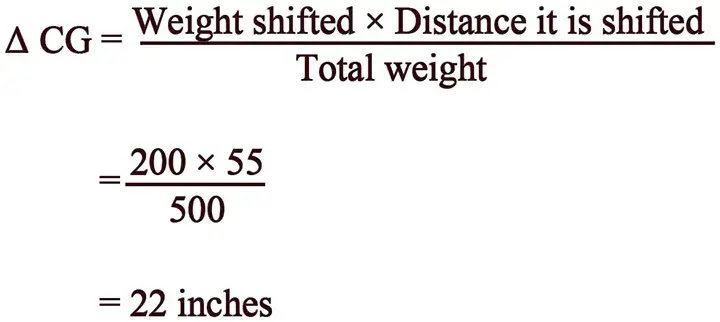
The CG of the lever in Figure 11 was 72 inches from the datum. This CG can be shifted to the center of the lever as in Figure 13 by moving weight B. If the 200-pound weight B is moved 55 inches to the left, the CG shifts from +72 inches to +50 inches, a distance of 22 inches.
When the distance the weight is to be shifted is known, the amount of weight to be shifted to move the CG to any location can be determined by another arrangement of the basic equation. Use the following arrangement of the formula to determine the amount of weight that has to be shifted from station 8 to station +25, to move the CG from station +72 to station +50.

If the 200-pound weight B is shifted from station +80 to station +25, the CG moves from station +72 to station +50.
A third arrangement of this basic equation is used to determine the amount the CG is shifted when a given amount of weight is moved for a specified distance (as it was done in Figure 11). The following formula is used to determine the amount the CG is shifted when 200-pound weight B is moved from +80 to +25.
Moving weight B from +80 to +25 moves the CG 22 inches from its original location at +72 to its new location at +50 as seen in Figure 13.
To complete the calculations, return to the original formula and enter the appropriate numbers.

The equation is balanced.
Mean Aerodynamic Chord
The CG point affects the stability of the aircraft. To ensure the aircraft is safe to fly, the CG must fall within specified limits established by the manufacturer.
On some aircraft, the CG is expressed as a percentage of the length of the mean aerodynamic chord (MAC) or “percent MAC.” [Figure 15] In order to make such a calculation, the position of the leading edge of the MAC must be known ahead of time.
 |
| Figure 15. Center of gravity expressed as percent mean aerodynamic chord |
CG limits are specified forward and aft and/or lateral (left and right) limits within which the aircraft’s CG must be located during flight. The area between the limits is called the CG range of the aircraft.
The position of the fore and aft CG limits is measured as a percentage of MAC from the MAC leading edge. Usually for a single or two-seat aircraft, the most forward position would be forward of 30–35 percent MAC. Thus, the allowable CG range in a light aircraft should not exceed 20 percent MAC.
Note: For a rectangular width of constant airfoil section dimensions, MAC is just the chord. For a symmetrically-tapered wing, it is the average of the root chord and the tip chord.
FAA-Furnished Weight and Balance Information
The information discussed to this point can be readily applied to any aircraft weight and balance problem. To apply the techniques, certain elements of information are required. This information is obtained from both FAA documents and manufacturer provided data.
Before an aircraft CG can be computed, certain information must be known. This information, furnished by the FAA for every certificated aircraft in the Type Certificate Data Sheets (TCDS) or Aircraft Specifications, can be accessed at www.faa.gov. When the design of an aircraft is approved by the FAA, an Approved Type Certificate and TCDS are issued. The TCDS includes all of the pertinent specification for the aircraft; at each annual or 100-hour inspection, it is the responsibility of the inspecting mechanic or repairman to ensure that the aircraft adheres to them. A note about the TCDS: aircraft certificated before January 1, 1958, were issued Aircraft Specifications under the Civil Air Regulations (CARs), but when the Civil Aeronautical Administration (CAA) was replaced by the FAA, Aircraft Specification were replaced by the TCDS.
The weight and balance information on a TCDS includes CG range, empty weight CG range (EWCG), maximum weights, number of seats, maximum baggage, fuel capacity, oil capacity, and datum location. Data pertinent to an individual model is located in its respective section of the TCDS.
 |
| Figure 16. Sample excerpt from TCDS A00009CH |
 |
| Figure 16. Sample excerpt from TCDS A00009CH (continued) |
 |
| Figure 16. Sample excerpt from TCDS A00009CH (continued) |
 |
| Figure 16. Sample excerpt from TCDS A00009CH (continued) |
 |
| Figure 16. Sample excerpt from TCDS A00009CH (continued) |
CG Range
S/N 1005 through 1147:Forward Limits: 138.7 inches at 2,110 lb with a straight line taper to 141.0 in at 2,694 lb and 143.0 in at 2,900 lb
Aft Limits: 144.6 in at 2,110 lb, with straight line taper to 147.4 in at 2,570 lb, and to 147.9 in at 2,745 lb, and 148.2 in at 2,900 lb
S/N 1148 through 1877, 1879 through 1885, and S/N 1005 through 1147 if Cirrus Service Bulletin SB 20-01-00 is complied with:
Forward Limits: 138.7 in at 2,110 lb with a straight line taper to 141.0 in at 2,694 lb and 144.1 in at 3,000 lb
Aft Limits: 144.6 in at 2,110 lb, with straight line taper to 147.4 in at 2,570 lb, and to 148.1 in at 2,900 lb, and 148.0 in at 3,000 lb
S/N 1878, 1886 and Subsequent:
Forward Limits: 137.8 in at 2,100 lb with a straight line taper to 139.1 in at 2,700 lb, and to 140.7 in at 3,050 lb
Aft Limits: 148.1 in at 2,100 lb, with straight line to 148.1 in at 3,050 lb
Empty Weight CG Range (EWCG)
When all of the seats and baggage compartments are located close together, it is not possible (as long as the EWCG is located within the EWCG range) to legally load the aircraft so that its operational CG falls outside this allowable range. If the seats and baggage areas extend over a wide range, the EWCG range is listed as “None.”
Maximum Weights
The maximum allowable takeoff and landing weights and the maximum allowable ramp weight are given. This basic information may be altered by a note. Notes are found in data pertinent to all models. An example would be Note 6 at the end of Figure 16.
Number of Seats
The number of seats and their arms are given in such terms as: 4 (2 at 143.5 aft of datum, 2 at 180 aft of datum).Maximum Baggage
Maximum baggage for this model is 130 pounds at 208 inches.Fuel Capacity
This important information is given in such terms as: 60.5 gal at 153.75 in. Usable: 56 gal (See Note 1). Notes can be found in data pertinent to all models.
Oil Capacity (Wet Sump)
The quantity of the full oil supply and its arm are given: 8 quarts at 76.2 in.Data Pertinent to all Models
The location of the datum is specified and is described, for example, as: 100 inches in front of the forward face of the firewall bulkhead.
Manufacturer-Furnished Information
When an aircraft is initially certificated, its empty weight and EWCG are determined and recorded in the weight and balance record, such as the one shown in Figure 17. Notice that in this figure, the moment is expressed as “Moment (lb-in/1,000).” This is a moment index, which means that the moment, a very large number, has been divided by 1,000 to make it more manageable. The Weight-Shift Control, Powered Parachute, and Amateur-Built Aircraft — Weight and Balance Control post discusses moment indices in more detail.
 |
| Figure 17. Weight and balance report |
The aircraft is furnished with an equipment list, specifies all the required equipment and all equipment approved for installation in the aircraft. The weight and arm of all installed equipment are included on the list and checked prior to the aircraft leaving the factory.
When an aircraft mechanic or repairman adds or removes any item on the equipment list, he or she must change the weight and balance record to indicate the new empty weight and EWCG, and the equipment list is revised to show which equipment is actually installed. Figure 18 is from a comprehensive equipment list that includes all of the items of equipment approved for this particular model of aircraft.
 |
| Figure 18. Excerpt from a typical comprehensive equipment list |
 |
| Figure 18. Excerpt from a typical comprehensive equipment list (continued) |
The pilot’s operating handbook (POH) for each individual aircraft includes an aircraft-specific equipment list of the items from this master list. When any item is added to or removed from the aircraft, its weight and arm are determined in the equipment list and used to update the weight and balance record. The POH and airplane flight manual (AFM) also contain CG moment envelopes and loading graphs. In addition to the weight and balance report and equipment list, the manufacturer also provides a CG range chart. The CG range can be found in text form in the TCDS. The CG range chart is furnished in the POH.