Unlike portable hand-held extinguishers used in the cabin or flight deck, installed fire extinguishing systems are permanently built into the aircraft and automatically or manually discharge an extinguishing agent into protected fire zones. These systems are used in areas such as engine compartments, APUs, cargo compartments, and lavatories where rapid fire suppression is essential and direct access by the crew may not be possible.
Transport aircraft have fixed fire extinguishing systems installed in:
- Turbine engine compartments
- APU compartments
- Cargo and baggage compartments
- Lavatories
CO2 Fire Extinguishing Systems
Older aircraft with reciprocating engines used CO2 as an extinguishing agent, but all newer aircraft designs with turbine engines use Halon or equivalent extinguishing agent, such as halocarbon clean agents.
Halogenated Hydrocarbons Fire Extinguishing Systems
The fixed fire extinguisher systems used in most engine fire and cargo compartment fire protection systems are designed to dilute the atmosphere with an inert agent that does not support combustion. Many systems use perforated tubing or discharge nozzles to distribute the extinguishing agent. High rate of discharge (HRD) systems use open-end tubes to deliver a quantity of extinguishing agent in 1 to 2 seconds.
The most common extinguishing agent still used today is Halon 1301 because of its effective firefighting capability and relatively low toxicity (UL classification Group 6). Noncorrosive Halon 1301 does not affect the material it contacts and requires no cleanup when discharged. Halon 1301 is the current extinguishing agent for commercial aircraft but a replacement is under development. Halon 1301 cannot be produced anymore because it depletes the ozone layer. Halon 1301 will be used until a suitable replacement is developed. Some military aircraft use HCL-125 and the Federal Aviation Administration (FAA) is testing HCL-125 for use in commercial aircraft.
Containers
Fire extinguisher containers (HRD bottles) store a liquid halogenated extinguishing agent and pressurized gas (typically nitrogen). They are normally manufactured from stainless steel. Depending upon design considerations, alternate materials are available, including titanium. Containers are also available in a wide range of capacities. They are produced under Department of Transportation (DOT) specifications or exemptions. Most aircraft containers are spherical in design, which provides the lightest weight possible. However, cylindrical shapes are available where space limitations are a factor. Each container incorporates a temperature/pressure sensitive safety relief diaphragm that prevents container pressure from exceeding container test pressure in the event of exposure to excessive temperatures. [Figures 1 and 2]
 |
| Figure 1. Built-in non-portable fire extinguisher containers (HRD bottles) on an airliner |
 |
| Figure 2. Diagram of fire extinguisher containers (HRD bottles) |
Discharge Valves
Discharge valves are installed on the containers. A cartridge (squib) and frangible disk-type valve are installed in the outlet of the discharge valve assembly. Special assemblies having solenoid-operated or manually-operated seat-type valves are also available. Two types of cartridge disk-release techniques are used. Standard release-type uses a slug driven by explosive energy to rupture a segmented closure disc. For high temperature or hermetically sealed units, a direct explosive impact-type cartridge is used that applies fragmentation impact to rupture a prestressed corrosion resistant steel diaphragm. Most containers use conventional metallic gasket seals that facilitate refurbishment following discharge. [Figure 3]
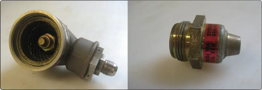 |
| Figure 3. Discharge valve (left) and cartridge, or squib (right) |
Pressure Indication
A wide range of diagnostics is utilized to verify the fire extinguisher agent charge status. A simple visual indication gauge is available, typically a helical bourdon-type indicator that is vibration resistant. [Figure 2] A combination gauge switch visually indicates actual container pressure and also provides an electrical signal if container pressure is lost, precluding the need for discharge indicators. A ground checkable diaphragm-type low-pressure switch is commonly used on hermetically sealed containers. The Kidde system has a temperature compensated pressure switch that tracks the container pressure variations with temperatures by using a hermetically sealed reference chamber.
Two-Way Check Valve
Two-way check valves are required in a two-shot system to prevent the extinguisher agent from a reserve container from backing up into the previous emptied main container. Valves are supplied with either MS-33514 or MS-33656 fitting configurations.
Discharge Indicators
Discharge indicators provide immediate visual evidence of container discharge on fire extinguishing systems. Two kinds of indicators can be furnished: thermal and discharge. Both types are designed for aircraft and skin mounting. [Figure 4]
 |
| Figure 4. Discharge indicators |
Thermal Discharge Indicator (Red Disk)
The thermal discharge indicator is connected to the fire container relief fitting and ejects a red disk to show when container contents have dumped overboard due to excessive heat. The agent discharges through the opening left when the disk blows out. This gives the flight and maintenance crews an indication that the fire extinguisher container needs to be replaced before next flight.
Yellow Disk Discharge Indicator
If the flight crew activates the fire extinguisher system, a yellow disk is ejected from the skin of the aircraft fuselage. This is an indication for the maintenance crew that the fire extinguishing system was activated by the flight crew, and the fire extinguishing container needs to be replaced before next flight.
Fire Switch
The engine and APU fire switches are typically installed on the center overhead panel or center console in the flight deck. [Figure 5] When an engine fire switch is activated, the following happens: the engine stops because the fuel control shuts off, the engine is isolated from the aircraft systems, and the fire extinguishing system is activated. Some aircraft use fire switches that need to be pulled and turned to activate the system, while others use a push-type switch with a guard. To prevent accidental activation of the fire switch, a lock is installed that releases the fire switch only when a fire has been detected. This lock can be manually released by the flight crew if the fire detection system malfunctions. [Figure 6]
 |
| Figure 5. Engine and APU fire switches on the cockpit center overhead panel |
 |
| Figure 6. Engine fire switch operation |