All aircraft fuel systems have filters and strainers to ensure that the fuel delivered to the engine(s) is free from contaminants. The first of these is located at the outlet of the fuel tank. A sump is used to encourage the collection of debris in the lowest part of the tank, which can then be drained off before flight. The actual tank outlet for the fuel is positioned above this sump.
Some type of screen is used to trap contaminants attempting to flow out of the tank into the fuel system. Finger screens are common on light aircraft. They increase the effective area of the fuel tank outlet, allowing a large amount of debris to be trapped while still permitting fuel to flow.
Figure 1 illustrates finger screens that are screwed into a fitting welded in the tank outlet.
 |
| Figure 1. Fuel tank outlet finger strainers are used in light aircraft |
Fuel tank outlet screens on aircraft with more complex fuel systems are similarly designed. When in-tank boost pumps are used, the tank outlet strainer is located at the inlet to the boost pump as shown in Figure 2.
 |
| Figure 2. A typical fuel boost pump inlet screen installation for a centrifugal pump mounted outside of the bottom of the tank |
The screen’s large area allows debris capture while still permitting sufficient fuel flow for operation. Regularly scheduled inspection and cleaning of these strainers are required.
An additional main strainer for the aircraft fuel system is required between the fuel tank outlet and the fuel metering device (in a carburetor or fuel-injection system). It is normally located between the fuel tank and the engine-driven fuel pump at the low point in the fuel system and is equipped with a drain for preflight sampling and draining.
On light aircraft, the main strainer may be in the form of a gascolator. A gascolator is a fuel strainer, or filter, that also incorporates a sediment collection bowl. The bowl is traditionally glass to allow quick visual checks for contaminants; however, many gascolators also have opaque bowls. A gascolator has a drain, or the bowl can be removed to inspect and discard trapped debris and water. [Figure 3]
 |
| Figure 3. A gascolator is the main fuel strainer between the fuel tanks and the fuel metering device on many light aircraft |
The main fuel strainer is often mounted at a low point on the engine firewall. The drain is accessible through an easy-access panel, or it simply extends through the bottom engine cowling. As with most filters or strainers, fuel is allowed to enter the unit but must travel up through the filtering element to exit.
Water, which is heavier than fuel, becomes trapped and collects in the bottom of the bowl. Other debris too large to pass through the element also settles in the strainer bowl.
Higher performance light aircraft may have a main filter/strainer. [Figure 4] On twin-engine aircraft, there is a main strainer for each engine. As with single-engine aircraft, a strainer is often mounted low on the engine firewall in each nacelle.
 |
| Figure 4. A filter assembly on a light twin reciprocating-engine aircraft |
Other larger fuel filters have double-screen construction. A cylindrical structural screen is wrapped with a fine mesh material through which inlet fuel must pass. Inside the cylinder is an additional cone-shaped screen.
Fuel must pass up through the cone to get to the filter outlet. The mesh used in this filter assembly prevents water and particles from exiting the filter bowl. The contaminants collect at the bottom to be drained off through a drain valve. [Figure 5]
 |
| Figure 5. A large-area double-screen filter passes fuel through the outer cylindrical mesh and the inner conical mesh |
Turbine engine fuel control units are extremely close-tolerance devices. It is imperative that fuel delivered to them is clean and contaminant free. The use of micronic filters makes this possible.
The replaceable cellulose filter mesh shown in Figure 6 can trap particles ranging from 10 to 200 microns in size and also absorbs water if present.
 |
| Figure 6. A typical micronic fuel filter with changeable cellulose filter element |
The small size of the mesh raises the possibility of the filter being blocked by debris or water. Therefore, a relief valve is included in the filter assembly to bypass fuel should pressure build up due to blockage.
Fuel filters are often used between the engine-driven fuel pump and the fuel metering device on reciprocating, as well as turbine-engine aircraft. While these are technically part of the engine fuel system, a common type used on turbine engines is discussed here.
It is also a micronic filter. It uses finely meshed discs or wafers stacked on a central core. These filters are able to withstand the higher pressure found in the engine fuel system downstream of the engine-driven pump. [Figure 7]
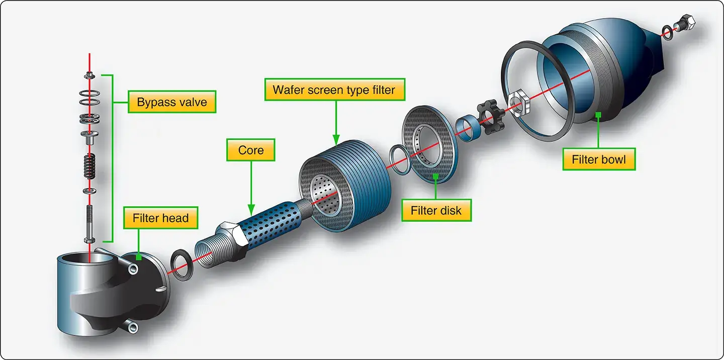 |
| Figure 7. A micronic wafer filter uses multiple screen wafers through which fuel must pass to exit the filter through the core. A spring loaded bypass valve in the filter housing unseats when the filter is clogged to continue delivery of fuel |
Indication of a filter blockage may also appear in the flight deck through the use of a bypass-activated switch or a pressure differential switch. A high fuel differential pressure indicates a blockage to the fuel filter.
The bypass valve physically activates a switch that closes the circuit to the annunciator in the first type. The differential pressure type indicator compares the input pressure of the fuel filter to the output pressure. A circuit is completed when a preset difference occurs.
Thus, an indicator is illuminated should a blockage cause the bypass to open or the inlet and outlet pressures to vary significantly. Fuel temperature can also be monitored to detect the possibility of filter blockage caused by ice formation from frozen water.