Aircraft fuel pumps are used to deliver fuel from the tanks to the engine under the pressure and flow conditions required for safe operation. Different pump designs are used depending on the aircraft fuel system configuration, engine type, and operational requirements. Fuel pumps may be hand operated, electrically driven, or engine driven.
Hand-Operated Fuel Pumps
Some older reciprocating engine aircraft have been equipped with hand-operated fuel pumps. They are used to back up the engine-driven pump and to transfer fuel from tank to tank. The wobble pumps, as they are known, are double-acting pumps that deliver fuel with each stroke of the pump handle.
They are essentially vane-type pumps that have bored passages in the center of the pump, allowing a back-and-forth motion to pump the fuel rather than a full revolution of the vanes as is common in electrically driven or engine-driven vane-type pumps. Figure 1 illustrates the mechanism found in a wobble pump.
 |
| Figure 1. A hand-operated wobble pump used for engine starting and fuel transfer on older transport category aircraft |
As the handle is moved down from where it is shown, the vane on the left side of the pump moves up, and the vane on the right side of the pump moves down. As the left vane moves up, it draws fuel into chamber A. Because chambers A and D are connected through the bored center, fuel is also drawn into chamber D.
At the same time, the right vane forces fuel out of chamber B, through the bored passage in the center of the pump, into chamber C and out the fuel outlet through the check valve at the outlet of chamber C. When the handle is moved up again, the left vane moves down, forcing fuel out of chambers A and D because the check valve at the inlet of the A chamber prevents fuel from flowing back through the fuel inlet. The right vane moves up simultaneously and draws fuel into chambers B and C.
While simple with little to go wrong, a hand-operated pump requires fuel lines to be run into the flight deck to the pump, creating a potential hazard that can be avoided by the use of an electrically driven pump. Modern light reciprocating-engine aircraft usually use electric auxiliary pumps, but they often make use of a simple hand pump for priming the engine(s) during starting.
These simple devices are single-acting piston pumps that pull fuel into the pump cylinder when the primer knob is pulled aft. When pushed forward, the fuel is pumped through lines to the engine cylinders. [Figure 2]
 |
| Figure 2. This engine primer pump is a hand-operated piston type. It is mounted in the instrument panel and extends through the firewall where fuel intake and delivery lines are attached to the fittings on the left |
Centrifugal Boost Pumps
The most common type of auxiliary fuel pump used on aircraft, especially large and high performance aircraft, is the centrifugal pump. It is electric motor driven and most frequently is submerged in the fuel tank or located just outside of the bottom of the tank with the inlet of the pump extending into the tank.
If the pump is mounted outside the tank, a pump removal valve is typically installed so the pump can be removed without draining the fuel tank. [Figure 3]
 |
| Figure 3. A centrifugal fuel boost pump can be submersed in the fuel tank (A) or can be attached to the outside of the tank with inlet and outlet plumbing extending into the tank (B). The pump removal valve handle extends below the warning flag clearance panel to indicate the pump inlet is closed |
A centrifugal boost pump is a variable displacement pump. It takes in fuel at the center of an impeller and expels it to the outside as the impeller turns. [Figure 4]
 |
| Figure 4. The internal workings of a centrifugal fuel boost pump. Fuel is drawn into the center of the impeller through a screen. It is moved to the outside of the case by the impeller and out the fuel outlet tube |
An outlet check valve prevents fuel from flowing back through the pump. A fuel feed line is connected to the pump outlet. A bypass valve may be installed in the fuel feed system to allow the engine-driven pump to pull fuel from the tank if the boost pump is not operating.
The centrifugal boost pump is used to supply the engine-driven fuel pump, back up the engine-driven fuel pump, and transfer fuel from tank to tank if the aircraft is so designed.
Some centrifugal fuel pumps operate at more than one speed, as selected by the pilot, depending on the phase of aircraft operation. Single-speed fuel pumps are also common. Centrifugal fuel pumps located in fuel tanks ensure positive pressure throughout the fuel system regardless of temperature, altitude, or flight attitude thus preventing vapor lock.
Submerged pumps have fuel proof covers for the electric motor since the motor is in the fuel. Centrifugal pumps mounted on the outside of the tank do not require this but have some sort of inlet that is located in the fuel. This can be a tube in which a shutoff valve is located so the pump can be changed without draining the tank.
The inlet of both types of centrifugal pump is covered with a screen to prevent the ingestion of foreign matter. [Figure 5]
 |
| Figure 5. A typical fuel boost pump inlet screen installation for a centrifugal pump mounted outside of the bottom of the tank |
Ejector Pumps
Fuel tanks with in-tank fuel pumps, such as centrifugal pumps, are constructed to maintain a fuel supply to the pump inlet at all times. This ensures that the pump does not cavitate and that the pump is cooled by the fuel.
The section of the fuel tank dedicated for the pump installation may be partitioned off with baffles that contain check valves, also known as flapper valves. These allow fuel to flow inboard to the pump during maneuvers but do not allow it to flow outboard.
Some aircraft use ejector pumps to help ensure that liquid fuel is always at the inlet of the pump. A relatively small diameter line circulates pump outflow back into the section of the tank where the pump is located. The fuel is directed through a venturi that is part of the ejector.
As the fuel rushes through the venturi, a low-pressure area is created. An inlet, or line that originates outside of the tank pump area, allows fuel to be drawn into the ejector assembly where it is pumped into the fuel pump tank section. Together with baffle check valves, ejector pumps maintain a positive head of fuel at the pump inlet. [Figure 6]
 |
| Figure 6. An ejector pump uses a venturi to draw fuel into the boost pump sump area of the fuel tank |
Pulsating Electric Pumps
General aviation aircraft often make use of smaller, less expensive auxiliary fuel pumps. The pulsating electric pump, or plunger-type fuel pump, is common. It is usually used in the same manner as a centrifugal fuel pump on larger aircraft, except it is located downstream of the fuel tank outlets.
The pulsating electric fuel pump is plumbed in parallel with the engine-driven pump. During starting, it provides fuel before the engine-driven fuel pump is up to speed, and it can be used during takeoff as a backup. It also can be used at high altitudes to prevent vapor lock.
The pulsating electric pump uses a plunger to draw fuel in and push fuel out of the pump. It is powered by a solenoid that alternates between being energized and de-energized, which moves the plunger back and forth in a pulsating motion. Figure 7 shows the internal workings of the pump.
 |
| Figure 7. A pulsating electric auxiliary fuel pump is used on many light reciprocating engine aircraft. In A, the pump is shown with its solenoid coil energized, which draws the plunger down between the coil. This opens the breaker points allowing the calibrated spring to push the plunger upwards, thus pumping fuel out the outlet B. This cycle repeats at a speed related to the fuel pressure buildup at the pump outlet |
When switched ON, current travels through the solenoid coils, which pull the steel plunger down between the coils. Any fuel in chamber C is forced through the small check valve in the center of the plunger and into chamber D.
When positioned between the solenoid coils, the plunger is far enough away from the magnet that it no longer attracts it, and the pivot allows the contacts to open. This disrupts the current to the solenoid.
The calibrated spring shown under the plunger is then strong enough to push the plunger up from between the solenoid coils. As the plunger rises, it pushes fuel in chamber D out the pump outlet port. Also, as the plunger rises, it draws fuel into chamber C through the inlet check valve.
As the plunger rises, the magnet is attracted to it and the upward motion closes the points. This allows current flow to the solenoid coils, and the process begins again with the plunger pulled down between the coils, the magnet releasing, and the points opening.
The single-acting pulsating electric fuel pump responds to the pressure of the fuel at its outlet. When fuel is needed, the pump cycles rapidly with little pressure at the pump outlet. As fuel pressure builds, the pump slows because the calibrated spring meets this resistance while attempting to force the piston upwards. A spring in the center of the plunger dampens its motion. A diaphragm separating chamber D fuel from an airspace at the top of the pump dampens the output fuel pulses.
Vane-Type Fuel Pumps
Vane-type fuel pumps (engine-driven fuel pumps) are the most common types of fuel pumps found on reciprocating-engine aircraft. They are used as both engine-driven primary fuel pumps and as auxiliary or boost pumps.
Regardless, the vane-type pump is a constant displacement pump that moves a constant volume of fuel with each revolution of the pump. When used as an auxiliary pump, an electric motor rotates the pump shaft. On engine-driven applications, the vane pump is typically driven by the accessory gearbox.
As with all vane pumps, an eccentric rotor is driven inside a cylinder. Slots on the rotor allow vanes to slide in and out and be held against the cylinder wall by a central floating spacer pin. As the vanes rotate with the eccentric rotor, the volume created by the cylinder wall, rotor, and vanes increases and then decreases.
An inlet port is located where the vanes create an increasing volume space, and fuel is drawn into the pump. Further around in the rotation, the space created becomes smaller. An outlet port located there causes fuel to be forced from the cylinder. [Figure 8]
 |
| Figure 8. The basic mechanism of a vane-type fuel pump |
The engine-driven fuel pump delivers more fuel than the engine needs to operate. However, the constant volume of a vane pump can be excessive. To regulate flow, most vane pumps have an adjustable pressure relief feature.
It uses pressure built up at the outlet of the pump to lift a valve off its seat, which returns excess fuel to the inlet side of the pump. Figure 9 shows a typical vane-type fuel pump with this adjustable pressure relief function.
 |
| Figure 9. The pressure relief valve in a vane-type fuel pump |
By setting the relief at a certain pressure above the engine fuel metering device air intake pressure, the correct volume of fuel is delivered. The relief pressure is set by a pressure adjustment screw that controls the tension of the relief valve spring.
During engine starting, or if the vane pump is inoperative, fuel must be able to flow through the pump to the fuel metering device. This is accomplished with the use of a bypass valve inside the pump. A lightly sprung plate under the relief valve overcomes spring pressure whenever the pump’s inlet fuel pressure is greater than the outlet fuel pressure. The plate moves down, and fuel can flow through the pump. [Figure 10]
 |
| Figure 10. The bypass feature in a vane-type fuel pump allows fuel to flow through the pump during starting or when the pump is inoperative |
Compensated vane-type fuel pumps are used when the vane pump is the engine-driven primary fuel pump. The relief valve setting varies automatically to provide the correct delivery of fuel as the air inlet pressure of the fuel metering device changes due to altitude or turbocharger outlet pressure.
A vent chamber above a diaphragm attached to the relief mechanism is connected to the inlet air pressure source. As air pressure varies, the diaphragm assists or resists the relief valve spring pressure, resulting in proper fuel delivery for the condition at the fuel metering device. [Figure 11]
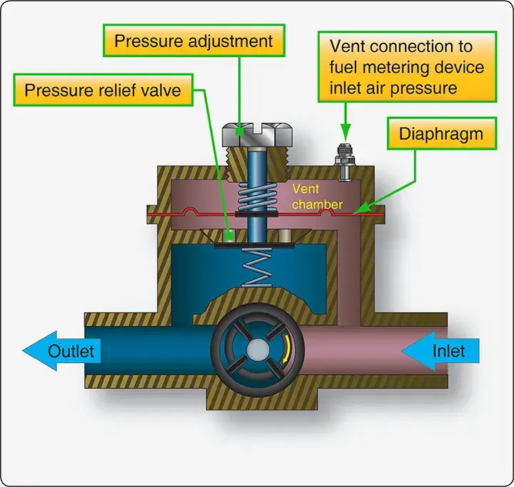 |
| Figure 11. A compensated vane pump is used in engine-driven applications. The fuel metering device inlet air pressure is connected to the vent chamber in the pump. The diaphragm assists or resists the relief valve mechanism depending on the pressure sensed in this chamber |