There are many different designs of shock struts, but most operate in a similar manner. The following discussion is general in nature. For information on the construction, operation, and servicing of a specific aircraft shock, consult the manufacturer’s maintenance instructions.
A typical pneumatic/hydraulic shock strut uses compressed air or nitrogen combined with hydraulic fluid to absorb and dissipate shock loads. It is sometimes referred to as an air/oil or oleo strut. A shock strut is constructed of two telescoping cylinders or tubes that are closed on the external ends. The upper cylinder is fixed to the aircraft and does not move. The lower cylinder is called the piston and is free to slide in and out of the upper cylinder. Two chambers are formed. The lower chamber is always filled with hydraulic fluid and the upper chamber is filled with compressed air or nitrogen. An orifice located between the two cylinders provides a passage for the fluid from the bottom chamber to enter the top cylinder chamber when the strut is compressed. [Figure 1]
 |
| Figure 1. A landing gear shock strut with a metering pin to control the flow of hydraulic fluid from the lower chamber to the upper chamber during compression |
Most shock struts employ a metering pin similar to that shown in Figure 1 for controlling the rate of fluid flow from the lower chamber into the upper chamber. During the compression stroke, the rate of fluid flow is not constant. It is automatically controlled by the taper of the metering pin in the orifice. When a narrow portion of the pin is in the orifice, more fluid can pass to the upper chamber. As the diameter of the portion of the metering pin in the orifice increases, less fluid passes. Pressure build-up caused by strut compression and the hydraulic fluid being forced through the metered orifice causes heat. This heat is converted from impact energy. It is dissipated through the structure of the strut.
On some types of shock struts, a metering tube is used. The operational concept is the same as that in shock struts with metering pins, except the holes in the metering tube control the flow of fluid from the bottom chamber to the top chamber during compression. [Figure 2]
 |
| Figure 2. Some landing gear shock struts use an internal metering tube rather than a metering pin to control the flow of fluid from the bottom cylinder to the top cylinder |
Upon liftoff or rebound from compression, the shock strut tends to extend rapidly. This could result in a sharp impact at the end of the stroke and damage to the strut. It is typical for shock struts to be equipped with a damping or snubbing device to prevent this. A recoil valve on the piston or a recoil tube restricts the flow of fluid during the extension stroke, which slows the motion and prevents damaging impact forces.
Most shock struts are equipped with an axle as part of the lower cylinder to provide installation of the aircraft wheels. Shock struts without an integral axle have provisions on the end of the lower cylinder for installation of the axle assembly. Suitable connections are provided on all shock strut upper cylinders to attach the strut to the airframe. [Figure 3]
 |
| Figure 3. Axles machined out of the same material as the landing gear lower cylinder |
The upper cylinder of a shock strut typically contains a valve fitting assembly. It is located at or near the top of the cylinder. The valve provides a means of filling the strut with hydraulic fluid and inflating it with air or nitrogen as specified by the manufacturer. A packing gland is employed to seal the sliding joint between the upper and lower telescoping cylinders. It is installed in the open end of the outer cylinder. A packing gland wiper ring is also installed in a groove in the lower bearing or gland nut on most shock struts. It is designed to keep the sliding surface of the piston from carrying dirt, mud, ice, and snow into the packing gland and upper cylinder. Regular cleaning of the exposed portion of the strut piston helps the wiper do its job and decreases the possibility of damage to the packing gland, which could cause the strut to leak.
To keep the piston and wheels aligned, most shock struts are equipped with torque links or torque arms. One end of the links is attached to the fixed upper cylinder. The other end is attached to the lower cylinder (piston) so it cannot rotate. This keeps the wheels aligned. The links also retain the piston in the end of the upper cylinder when the strut is extended, such as after takeoff. [Figure 4]
 |
| Figure 4. Torque links align the landing gear and retain the piston in the upper cylinder when the strut is extended |
Nose gear shock struts are provided with a locating cam assembly to keep the gear aligned. A cam protrusion is attached to the lower cylinder, and a mating lower cam recess is attached to the upper cylinder. These cams line up the wheel and axle assembly in the straight-ahead position when the shock strut is fully extended. This allows the nose wheel to enter the wheel well when the nose gear is retracted and prevents structural damage to the aircraft. It also aligns the wheels with the longitudinal axis of the aircraft prior to landing when the strut is fully extended. [Figure 5] Many nose gear shock struts also have attachments for the installation of an external shimmy damper. [Figure 6]
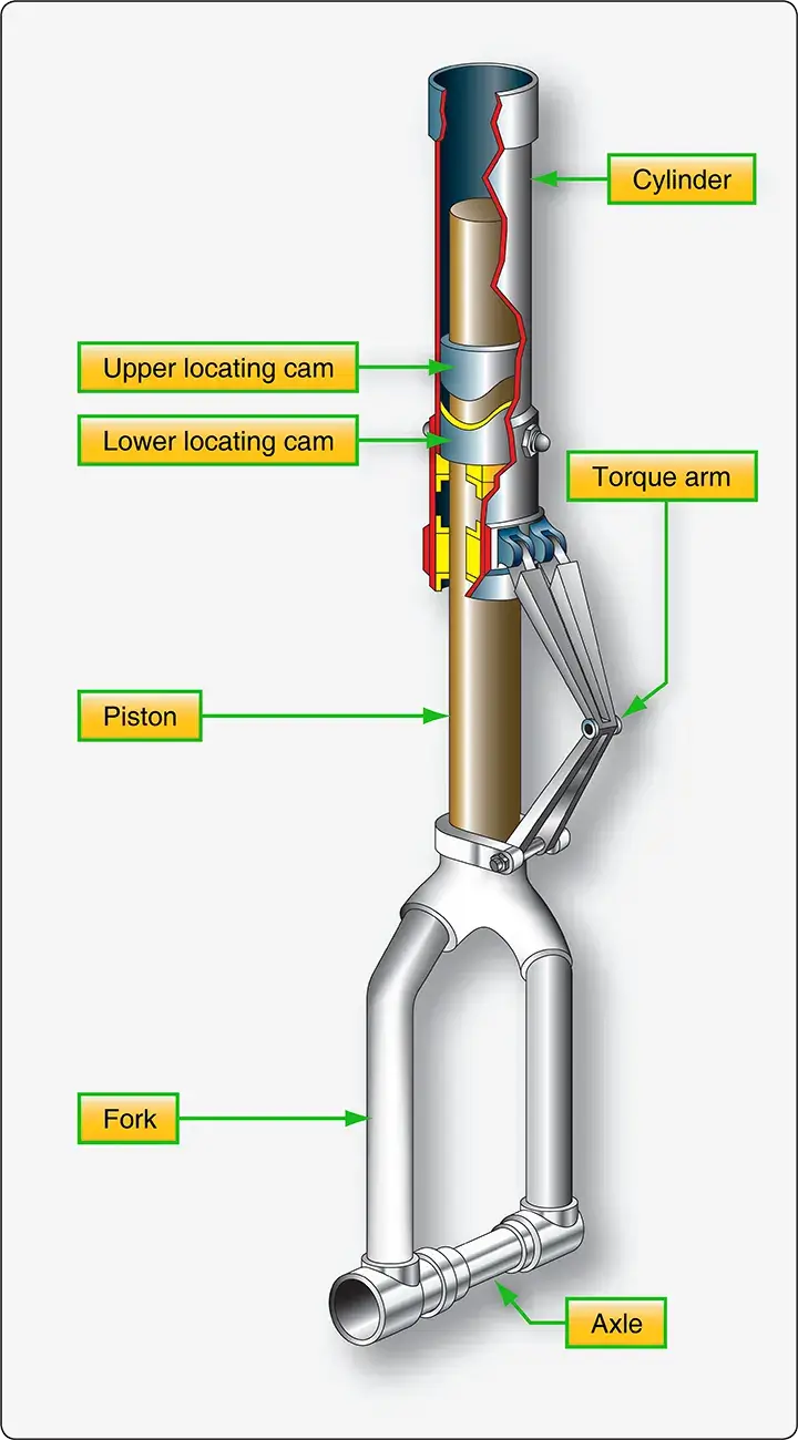 |
| Figure 5. An upper locating cam mates into a lower cam recess when the nose landing gear shock strut is extended before landing and before the gear is retracted into the wheel well |
 |
| Figure 6. A shimmy damper helps control oscillations of the nose gear |
Nose gear struts are often equipped with a locking or disconnect pin to enable quick turning of the aircraft while towing or positioning the aircraft when on the ramp or in a hangar. Disengagement of this pin allows the wheel fork spindle on some aircraft to rotate 360°, thus enabling the aircraft to be turned in a tight radius. At no time should the nose wheel of any aircraft be rotated beyond limit lines marked on the airframe.
Nose and main gear shock struts on many aircraft are also equipped with jacking points and towing lugs. Jacks should always be placed under the prescribed points. When towing lugs are provided, the towing bar should be attached only to these lugs. [Figure 7]
 |
| Figure 7. A towing lug on a landing gear is the designed means for attaching a tow bar |
Shock struts contain an instruction plate that gives directions for filling the strut with fluid and for inflating the strut. The instruction plate is usually attached near the filler inlet and air valve assembly. It specifies the correct type of hydraulic fluid to use in the strut and the pressure to which the strut should be inflated. It is of utmost importance to become familiar with these instructions prior to filling a shock strut with hydraulic fluid or inflating it with air or nitrogen.
Shock Strut Operation
Figure 8 illustrates the inner construction of a shock strut. Arrows show the movement of the fluid during compression and extension of the strut. The compression stroke of the shock strut begins as the aircraft wheels touch the ground. As the center of mass of the aircraft moves downward, the strut compresses, and the lower cylinder or piston is forced upward into the upper cylinder. The metering pin is therefore moved up through the orifice. The taper of the pin controls the rate of fluid flow from the bottom cylinder to the top cylinder at all points during the compression stroke. In this manner, the greatest amount of heat is dissipated through the walls of the strut. At the end of the downward stroke, the compressed air in the upper cylinder is further compressed which limits the compression stroke of the strut with minimal impact. During taxi operations, the air in the tires and the strut combine to smooth out bumps.
 |
| Figure 8. Fluid flow during shock strut operation is controlled by the taper of the metering pin in the shock strut orifice |
Insufficient fluid or air in the strut causes the compression stroke to not be properly limited. The strut could bottom out, resulting in impact forces to be transferred directly to the airframe through the metallic structure of the strut. In a properly serviced strut, the extension stroke of the shock strut operation occurs at the end of the compression stroke. Energy stored in the compressed air in the upper cylinder causes the aircraft to start moving upward in relation to the ground and lower strut cylinder as the strut tries to rebound to its normal position. Fluid is forced back down into the lower cylinder through restrictions and snubbing orifices. The snubbing of fluid flow during the extension stroke dampens the strut rebound and reduces oscillation caused by the spring action of the compressed air. A sleeve, spacer, or bumper ring incorporated into the strut limits the extension stroke.
Efficient operation of the shock struts requires that proper fluid and air pressure be maintained. To check the fluid level, most struts need to be deflated and compressed into the fully compressed position. Deflating a shock strut can be a dangerous operation. The technician must be thoroughly familiar with the operation of the high-pressure service valve found at the top of the strut’s upper cylinder. Refer to the manufacturer’s instructions for proper deflating technique of the strut in question and follow all necessary safety precautions.
Two common types of high-pressure strut servicing valves are illustrated in Figure 9. The AN6287-1 valve in Figure 9-A has a valve core assembly and is rated to 3,000 pounds per square inch (psi). However, the core itself is only rated to 2,000 psi. The MS28889-1 valve in Figure 9-B has no valve core. It is rated to 5,000 psi. The swivel nut on the AN6287-1 valve is smaller than the valve body hex. The MS28889-1 swivel nut is the same size as the valve body hex. The swivel nuts on both valves engage threads on an internal stem that loosens or draws tight the valve stem to a metal seat.
 |
| Figure 9. Valve core-type (A) and core-free valve fittings (B) are used to service landing gear shock struts |
Servicing Shock Struts
The following procedures are typical of those used in deflating a shock strut, servicing it with hydraulic fluid, and re-inflating the strut.
- Position the aircraft so that the shock struts are in the normal ground operating position. Make certain that personnel, work stands, and other obstacles are clear of the aircraft. If the maintenance procedures require, securely jack the aircraft.
- Remove the cap from the air servicing valve. [Figure 10-A]
- Check the swivel nut for tightness.
- If the servicing valve is equipped with a valve core, depress it to release any air pressure that may be trapped under the core in the valve body. [Figure 10-B] Always be positioned to the side of the trajectory of any valve core in case it releases. Propelled by strut air pressure, serious injury could result.
- Loosen the swivel nut. For a valve with a valve core (AN6287-1), rotate the swivel nut one turn (counterclockwise). Using a tool designed for the purpose, depress the valve core to release all of the air in the strut. For a valve without a valve core (MS28889), rotate the swivel nut sufficiently to allow the air to escape.
- When all air has escaped from the strut, it should be compressed completely. Aircraft on jacks may need to have the lower strut jacked with an exerciser jack to achieve full compression of the strut. [Figure 11]
- Remove the valve core of an AN6287 valve [Figure 10-D] using a valve core removal tool. [Figure 12] Then, remove the entire service valve by unscrewing the valve body from the strut. [Figure 10-E]
- Fill the strut with hydraulic fluid to the level of the service valve port with the approved hydraulic fluid.
- Re-install the air service valve assembly using a new O-ring packing. Torque according to applicable manufacturer’s specifications. If an AN6287-1valve, install a new valve core.
- Inflate the strut. A threaded fitting from a controlled source of high pressure air or nitrogen should be screwed onto the servicing valve. Control the flow with the service valve swivel nut. The correct amount of inflation is measured in psi on some struts. Other manufacturers specify struts to be inflated until extension of the lower strut is a certain measurement. Follow manufacturer’s instructions. Shock struts should always be inflated slowly to avoid excess heating and over inflation.
- Once inflated, tighten the swivel nut and torque as specified.
- Remove the fill hose fitting and finger tighten the valve cap of the valve.
 |
| Figure 10. Steps in servicing a landing gear shock strut include releasing the air from the strut and removing the service valve from the top of the strut to permit the introduction of hydraulic fluid. Note that the strut is illustrated horizontally. On an actual aircraft installation, the strut is serviced in the vertical position (landing gear down) |
 |
| Figure 11. Air trapped in shock strut hydraulic fluid is bled by exercising the strut through its full range of motion while the end of an air-tight bleed hose is submerged in a container of hydraulic fluid |
 |
| Figure 12. This valve tool features internal and external thread chasers, a notched valve core removal/installation tool, and a tapered end for depressing a valve core or clearing debris |
Bleeding Shock Struts
It may be necessary to bleed a shock strut during the service operation or when air becomes trapped in the hydraulic fluid inside the strut. This can be caused by low hydraulic fluid quantity in the strut. Bleeding is normally done with the aircraft on jacks to facilitate repeated extension and compression of the strut to expel the entrapped air. An example procedure for bleeding the shock strut follows.
- Construct and attach a bleed hose containing a fitting suitable for making an airtight connection at the shock strut service valve port. Ensure a long enough hose to reach the ground while the aircraft is on jacks.
- Jack the aircraft until the shock struts are fully extended.
- Release any air pressure in the shock strut.
- Remove the air service valve assembly.
- Fill the strut to the level of the service port with approved hydraulic fluid.
- Attach the bleed hose to the service port and insert the free end of the hose into a container of clean hydraulic fluid. The hose end must remain below the surface of the fluid.
- Place an exerciser jack or other suitable jack under the shock strut jacking point. Compress and extend the strut fully by raising and lowering the jack. Continue this process until all air bubbles cease to form in the container of hydraulic fluid. Compress the strut slowly and allow it to extend by its own weight.
- Remove the exerciser jack. Lower the aircraft and remove all other jacks.
- Remove the bleed hose assembly and fitting from the service port of the strut.
- Install the air service valve, torque, and inflate the shock strut to the manufacturer’s specifications.