Work
A physicist defines work as force times distance. Work done by a force acting on a body is equal to the magnitude of the force multiplied by the distance through which the force acts.Work (W) = Force (F) × Distance (D)
Work is measured by several standards. The most common unit is called foot-pound (ft-lb). If a one-pound mass is raised one foot, one ft-lb of work has been performed. The greater the mass is and/or the greater the distance is, the greater the work performed.
Horsepower
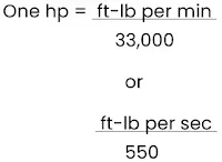
The common unit of mechanical power is the horsepower (hp). Late in the 1 8th century, James Watt, the inventor of the steam engine, found that an English workhorse could work at the rate of 550 ft-lb per second, or 33,000 ft-lb per minute, for a reasonable length of time. From his observations came the unit of horsepower, which is the standard unit of mechanical power in the English system of measurement. To calculate the hp rating of an engine, divide the power developed in ft-lb per minute by 33,000, or the power in ft-lb per second by 550.As stated above, work is the product of force and distance, and power is work per unit of time. Consequently, if a 33,000-lb weight is lifted through a vertical distance of 1 foot in 1 minute, the power expended is 33,000 ft-lb per minute, or exactly 1 hp.
Work is performed not only when a force is applied for lifting; force may be applied in any direction. If a 100-lb weight is dragged along the ground, a force is still being applied to perform work, although the direction of the resulting motion is approximately horizontal. The amount of this force would depend upon the roughness of the ground.
If the weight were attached to a spring scale graduated in pounds, then dragged by pulling on the scale handle, the amount of force required could be measured. Assume that the force required is 90 lb, and the 100-lb weight is dragged 660 feet in 2 minutes. The amount of work performed in the 2 minutes is 59,400 ft-lb or 29,700 ft-lb per minute. Since 1 hp is 33,000 ft-lb per minute, the hp expended in this case is 29,700 divided by 33,000, or 0.9 hp.
[ad-mid]
Piston Displacement
When other factors remain equal, the greater the piston displacement, the greater the maximum horsepower an engine is capable of developing. When a piston moves from BDC to TDC, it displaces a specific volume. The volume displaced by the piston is known as piston displacement and is expressed in cubic inches for most American-made engines and cubic centimeters for others.The piston displacement of one cylinder may be obtained by multiplying the area of the cross-section of the cylinder by the total distance the piston moves in the cylinder in one stroke. For multicylinder engines, this product is multiplied by the number of cylinders to get the total piston displacement of the engine.
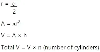
Since the volume (V) of a geometric cylinder equals the area (A) of the base multiplied by the height (h), it is expressed mathematically as:
V = A × h
The area of the base is the area of the cross-section of the cylinder.
Area of a Circle
To find the area of a circle, it is necessary to use a number called pi (π). This number represents the ratio of the circumference to the diameter of any circle. Pi cannot be stated exactly because it is a never-ending decimal. It is 3.1416 expressed to four decimal places, which is accurate enough for most computations.The area of a circle, as in a rectangle or triangle, must be expressed in square units. The distance that is one-half the diameter of a circle is known as the radius. The area of any circle is found by squaring the radius (r) and multiplying by π. The formula is:
The radius of a circle is equal to ½ the diameter:
Example
Compute the piston displacement of the PWA 14 cylinder engine having a cylinder with a 5.5 inch diameter and a 5.5 inch stroke. Formulas required are:
Compute the piston displacement of the PWA 14 cylinder engine having a cylinder with a 5.5 inch diameter and a 5.5 inch stroke. Formulas required are:
Substitute values into these formulas and complete the calculation.
Rounded off to the next whole number, total piston displacement equals 1,829 cubic inches.
Another method of calculating the piston displacement uses the diameter of the piston instead of the radius in the formula for the area of the base.
From this point on, the calculations are identical to the preceding example.
Compression Ratio
All internal combustion engines must compress the fuel/air mixture to receive a reasonable amount of work from each power stroke. The fuel/air charge in the cylinder can be compared to a coil spring in that the more it is compressed, the more work it is potentially capable of doing.The compression ratio of an engine is a comparison of the volume of space in a cylinder when the piston is at the bottom of the stroke to the volume of space when the piston is at the top of the stroke. [Figure 1] This comparison is expressed as a ratio, hence the term compression ratio. Compression ratio is a controlling factor in the maximum horsepower developed by an engine, but it is limited by present day fuel grades and the high engine speeds and manifold pressures required for takeoff. For example, if there are 140 cubic inches of space in the cylinder when the piston is at the bottom and there are 20 cubic inches of space when the piston is at the top of the stroke, the compression ratio would be 140 to 20. If this ratio is expressed in fraction form, it would be 140/20 or 7 to 1, usually represented as 7:1.
 |
| Figure 1. Compression ratio |
The limitations placed on compression ratios, manifold pressure, and the manifold pressure’s effect on compression pressures has a major effect on engine operation. Manifold pressure is the average absolute pressure of the air or fuel/ air charge in the intake manifold and is measured in units of inches of mercury ("Hg). Manifold pressure is dependent on engine speed (throttle setting) and the degree supercharging. The operation of the supercharger increases the weight of the charge entering the cylinder. When a true supercharger is used with the aircraft engine, the manifold pressure may be considerably higher than the pressure of the outside atmosphere. The advantage of this condition is that a greater amount of charge is forced into a given cylinder volume, and a greater output of horsepower results.
Compression ratio and manifold pressure determine the pressure in the cylinder in that portion of the operating cycle when both valves are closed. The pressure of the charge before compression is determined by manifold pressure, while the pressure at the height of compression (just prior to ignition) is determined by manifold pressure times the compression ratio. For example, if an engine were operating at a manifold pressure of 30 "Hg with a compression ratio of 7:1, the pressure at the instant before ignition would be approximately 210 "Hg. However, at a manifold pressure of 60 "Hg, the pressure would be 420 "Hg.
Without going into great detail, it has been shown that the compression event magnifies the effect of varying the manifold pressure, and the magnitude of both affects the pressure of the fuel charge just before the instant of ignition. If the pressure at this time becomes too high, pre-ignition or detonation occur and produce overheating. Pre-ignition is when the fuel air charge starts to burn before the spark plug fires. Detonation occurs when the fuel air charge is ignited by the spark plug, but instead of burning at a controlled rate, it explodes causing cylinder temperatures and pressures to spike very quickly. If this condition exists for very long, the engine can be damaged or destroyed.
One of the reasons for using engines with high compression ratios is to obtain long-range fuel economy, to convert more heat energy into useful work than is done in engines of low compression ratio. Since more heat of the charge is converted into useful work, less heat is absorbed by the cylinder walls. This factor promotes cooler engine operation, which in turn increases the thermal efficiency. Here again, a compromise is needed between the demand for fuel economy and the demand for maximum horsepower without detonation. Some manufacturers of high compression engines suppress detonation at high manifold pressures by using high octane fuel and limiting maximum manifold pressure.
[ad-long]
Indicated Horsepower
The indicated horsepower produced by an engine is the horsepower calculated from the indicated mean effective pressure and the other factors which affect the power output of an engine. Indicated horsepower is the power developed in the combustion chambers without reference to friction losses within the engine. This horsepower is calculated as a function of the actual cylinder pressure recorded during engine operation.To facilitate the indicated horsepower calculations, a mechanical indicating device, such as is attached to the engine cylinder scribes the actual pressure existing in the cylinder during the complete operating cycle. This pressure variation can be represented by the kind of graph shown in Figure 2. Notice that the cylinder pressure rises on the compression stroke, reaches a peak after top center, and decreases as the piston moves down on the power stroke. Since the cylinder pressure varies during the operating cycle, an average pressure (line AB) is computed. This average pressure, if applied steadily during the time of the power stroke, would do the same amount of work as the varying pressure during the same period. This average pressure is known as indicated mean effective pressure and is included in the indicated horsepower calculation with other engine specifications. If the characteristics and the indicated mean effective pressure of an engine are known, it is possible to calculate the indicated horsepower rating.
 |
| Figure 2. Compression ratio |
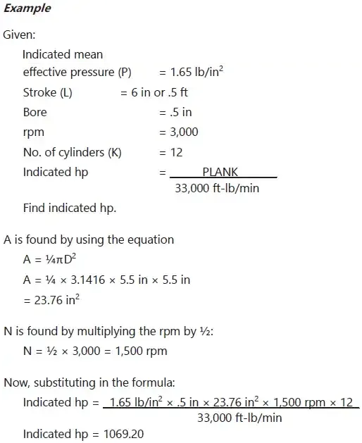
The indicated horsepower for a four-stroke cycle engine can be calculated from the following formula, in which the letter symbols in the numerator are arranged to spell the word “PLANK” to assist in memorizing the formula:
In the formula above, the area of the piston multiplied by the indicated mean effective pressure gives the force acting on the piston in pounds. This force multiplied by the length of the stroke in feet gives the work performed in one power stroke, which, multiplied by the number of power strokes per minute, gives the number of ft-lb per minute of work produced by one cylinder. Multiplying this result by the number of cylinders in the engine gives the amount of work performed, in ft-lb, by the engine. Since hp is defined as work done at the rate of 33,000 ft-lb per minute, the total number of ft-lb of work performed by the engine is divided by 33,000 to find the indicated horsepower.
Brake Horsepower
The indicated horsepower calculation discussed in the preceding paragraph is the theoretical power of a frictionless engine. The total horsepower lost in overcoming friction must be subtracted from the indicated horsepower to arrive at the actual horsepower delivered to the propeller. The power delivered to the propeller for useful work is known as brake horsepower (bhp). The difference between indicated and brake horsepower is known as friction horsepower, which is the horsepower required to overcome mechanical losses, such as the pumping action of the pistons, the friction of the pistons, and the friction of all other moving parts.The measurement of an engine’s bhp involves the measurement of a quantity known as torque or twisting moment. Torque is the product of a force and the distance of the force from the axis about which it acts, or
Torque = force × distance
(at right angles to the force)
Torque is a measure of load and is properly expressed in pound-inches (lb-in) or pound-feet (lb-ft). Torque should not be confused with work, which is expressed in inch-pounds (in-lb) or foot-pounds (ft-lb).
There are numerous devices for measuring torque, such as a dynamometer or a torque meter. One very simple type of device that can be used to demonstrate torque calculations is the Prony brake. [Figure 3]
 |
| Figure 3. Typical prony brake |
All of these torque-measuring devices are usable to calculate power output of an engine on a test stand. It consists essentially of a hinged collar, or brake, which can be clamped to a drum splined to the propeller shaft. The collar and drum form a friction brake, which can be adjusted by a wheel. An arm of a known length is rigidly attached to or is a part of the hinged collar and terminates at a point that rests on a set of scales. As the propeller shaft rotates, it tends to carry the hinged collar of the brake with it and is prevented from doing so only by the arm that rests on the scale. The scale indicates the force necessary to arrest the motion of the arm. If the resulting force registered on the scale is multiplied by the length of the arm, the resulting product is the torque exerted by the rotating shaft. For example, if the scale registers 200 pounds and the length of the arm is 3.18 feet, the torque exerted by the shaft is:
200 lb × 3.18 ft = 636 lb-ft
Once the torque is known, the work done per revolution of the propeller shaft can be computed without difficulty by the equation:
Work per revolution = 2π × torque
If work per revolution is multiplied by the rpm, the result is work per minute, or power. If the work is expressed in ft-lb per minute, this quantity is divided by 33,000. The result is the brake horsepower of the shaft.
As long as the friction between the brake collar and propeller shaft drum is great enough to impose an appreciable load on the engine, but is not great enough to stop the engine, it is not necessary to know the amount of friction between the collar and drum to compute the bhp. If there were no load imposed, there would be no torque to measure, and the engine would “run away.” If the imposed load is so great that the engine stalls, there may be considerable torque to measure, but there is no rpm. In either case, it is impossible to measure the bhp of the engine. However, if a reasonable amount of friction exists between the brake drum and the collar and the load is then increased, the tendency of the propeller shaft to carry the collar and arm about with it becomes greater, thus imposing a greater force upon the scales. As long as the torque increase is proportional to the rpm decrease, the horsepower delivered at the shaft remains unchanged. This can be seen from the equation in which 2πr and 33,000 are constants and torque and rpm are variables. If the change in rpm is inversely proportional to the change in torque, their product remains unchanged, and bhp remains unchanged. This is important. It shows that horsepower is the function of both torque and rpm, and can be changed by changing either torque, rpm, or both.
[ad-longer]
Friction Horsepower
Friction horsepower is the indicated horsepower minus brake horsepower. It is the horsepower used by an engine in overcoming the friction of moving parts, drawing in fuel, expelling exhaust, driving oil and fuel pumps, and other engine accessories. On modern aircraft engines, this power loss through friction may be as high as 10 to 15 percent of the indicated horsepower.Friction and Brake Mean Effective Pressures
The indicated mean effective pressure (IMEP), discussed previously, is the average pressure produced in the combustion chamber during the operating cycle and is an expression of the theoretical, frictionless power known as indicated horsepower. In addition to completely disregarding power lost to friction, indicated horsepower gives no indication of how much actual power is delivered to the propeller shaft for doing useful work. However, it is related to actual pressures that occur in the cylinder and can be used as a measure of these pressures.To compute the friction loss and net power output, the indicated horsepower of a cylinder may be thought of as two separate powers, each producing a different effect. The first power overcomes internal friction, and the horsepower thus consumed is known as friction horsepower. The second power, known as brake horsepower, produces useful work at the propeller. That portion of IMEP that produces brake horsepower is called brake mean effective pressure (BMEP). The remaining pressure used to overcome internal friction is called friction mean effective pressure (FMEP). [Figure 4] IMEP is a useful expression of total cylinder power output, but is not a real physical quantity; likewise, FMEP and BMEP are theoretical but useful expressions of friction losses and net power output.
 |
| Figure 4. Power and pressure |
Although BMEP and FMEP have no real existence in the cylinder, they provide a convenient means of representing pressure limits or rating engine performance throughout its entire operating range. There is an operating relationship between IMEP, BMEP, and FMEP.
One of the basic limitations placed on engine operation is the pressure developed in the cylinder during combustion. In the discussion of compression ratios and indicated mean effective pressure, it was found that, within limits, increased pressure resulted in increased power. It was also noted that if the cylinder pressure were not controlled within close limits, it would impose dangerous internal loads that might result in engine failure. Therefore, it is important to have a means of determining these cylinder pressures as a protective measure and for efficient application of power.
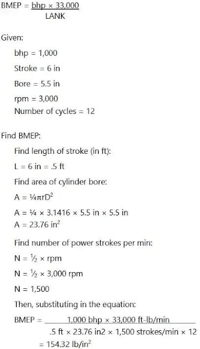
If the bhp is known, the BMEP can be computed by means of the following equation:
Thrust Horsepower
Thrust horsepower can be considered the result of the engine and the propeller working together. If a propeller could be designed to be 100 percent efficient, the thrust and the bph would be the same. However, the efficiency of the propeller varies with the engine speed, attitude, altitude, temperature, and airspeed. Thus, the ratio of the thrust horsepower and the bhp delivered to the propeller shaft will never be equal. For example, if an engine develops 1,000 bhp, and it is used with a propeller having 85 percent efficiency, the thrust horsepower of that engine-propeller combination is 85 percent of 1,000 or 850 thrust hp. Of the four types of horsepower discussed, it is the thrust horsepower that determines the performance of the engine-propeller combination.RELATED POSTS
- Aircraft Engines
- Engine General Requirements
- Types of Engines
- Reciprocating Engines
- Propeller Reduction Gearing and Propeller Shafts
- Reciprocating Engine Operating Principles
- Operating Cycles
- Reciprocating Engine Efficiencies


