Aircraft rigging is the process of adjusting, aligning, and securing aircraft structures and control systems to ensure proper operation and airworthiness. Correct rigging ensures that flight controls move through their specified range, structural components are properly aligned, and control systems operate smoothly and safely. Because even minor rigging errors can affect aircraft performance, handling characteristics, and safety, all rigging procedures must be performed in accordance with the manufacturer's specifications and approved maintenance practices.
Aircraft rigging involves the adjustment and travel of movable flight controls which are attached to aircraft major surfaces, such as wings and vertical and horizontal stabilizers. Ailerons are attached to the wings, elevators are attached to the horizontal stabilizer, and the rudder is attached to the vertical stabilizer. Rigging involves setting cable tension, adjusting travel limits of flight controls, and setting travel stops.
In addition to the flight controls, rigging is also performed on various components to include engine controls, flight deck controls, and retractable landing gear component parts. Rigging also includes the safetying of the attaching hardware using various types of cotter pins, locknuts, or safety wire.
Rigging Specifications
Type Certificate Data Sheet
The Type Certificate Data Sheet (TCDS) is a formal description of an aircraft, engine, or propeller. It is issued by the Federal Aviation Administration (FAA) when the FAA determines that the product meets the applicable requirements for certification under 14 CFR regulations. It lists the limitations and information required for type certification, including airspeed limits, weight limits, control surface movements, engine make and model, minimum crew, fuel type, thrust limits, rpm limits, etc., and the various components eligible for installation on the product.
Maintenance Manual
A maintenance manual is developed by the manufacturer of the applicable product and provides the recommended and acceptable procedures to be followed when maintaining or repairing that product. Maintenance personnel are required by regulation to follow the applicable instructions set forth by the manufacturer. The Limitations section of the manual lists “life limits” of the product or its components that must be complied with during inspections and maintenance.
Structural Repair Manual (SRM)
The structural repair manual is developed by the manufacturer’s engineering department to be used as a guideline to assist in the repair of common damage to a specific aircraft structure. It provides information for acceptable repairs of specific sections of the aircraft.
Manufacturer’s Service Information
Information from the manufacturer may be in the form of information bulletins, service instructions, service bulletins, service letters, etc., that the manufacturer publishes to provide instructions for product improvement. Service instructions may include a recommended modification or repair that precedes the issuance of an Airworthiness Directive (AD). Service letters may provide more descriptive procedures or revise sections of the maintenance manuals. They may also include instructions for the installation and repair of optional equipment, not listed in the Type Certificate Data Sheet (TCDS).
Airplane Assembly
Aileron Installation
The manufacturer’s maintenance and illustrated parts book must be followed to ensure the correct procedures and hardware are being used for installation of the control surfaces. All of the control surfaces require specific hardware, spacers, and bearings be installed to ensure the surface does not jam or become damaged during movement. After the aileron is connected to the flight deck controls, the control system must be inspected to ensure the cables/push-pull rods are routed properly. When a balance cable is installed, check for correct attachment and operation to determine the ailerons are moving in the proper direction and opposite each other.
Flap Installation
The design, installation, and systems that operate flaps are as varied as the models of airplanes on which they are installed. As with any system on a specific aircraft, the manufacturer’s maintenance manual and the illustrated parts book must be followed to ensure the correct procedures and parts are used. Simple flap systems are usually operated manually by cables and/or torque tubes. Typically, many of the smaller manufactured airplane designs have flaps that are actuated by torque tubes and chains through a gear box driven by an electric motor.
Empennage Installation
The empennage, consisting of the horizontal and vertical stabilizer, is not normally removed and installed, unless the aircraft was damaged. Elevators, rudders, and stabilators are rigged the same as any other control surface, using the instructions provided in the manufacturer’s maintenance manuals.
Control Operating Systems
Cable Systems
There are various types of cable:
- Material—aircraft control cables are fabricated from carbon steel or stainless (corrosion-resistant) steel. Additionally, some manufacturers use a nylon coated cable that is produced by extruding a flexible nylon coating over corrosion-resistant steel (CRES) cable. By adding the nylon coating to the corrosion-resistant steel cable, it increases the service life by protecting the cable strands from friction wear, keeping dirt and grit out, and dampening vibration which can work-harden the wires in long runs of cable.
- Cable construction—the basic component of a cable is a wire. The diameter of the wire determines the total diameter of the cable. A number of wires are preformed into a helical or spiral shape and then formed into a strand. These preformed strands are laid around a straight center strand to form a cable.
- Cable designations—based on the number of strands and wires in each strand. The 7 × 19 cable is made up of seven strands of 19 wires each. Six of these strands are laid around the center strand. This cable is very flexible and is used in primary control systems and in other locations where operation over pulleys is frequent. The 7 × 7 cable consists of seven strands of seven wires each. Six of these strands are laid around the center strand. This cable is of medium flexibility and is used for trim tab controls, engine controls, and indicator controls. [Figure 1]
 |
| Figure 1. Cable construction and cross-section |
Types of control cable termination include:
- Woven splice—a hand-woven 5-tuck splice used on aircraft cable. The process is very time consuming and produces only about 75 percent of the original cable strength. The splice is rarely used except on some antique aircraft where the effort is made to keep all parts in their original configuration.
- Nicopress® process—a patented process using copper sleeves and may be used up to the full rated strength of the cable when the cable is looped around a thimble. [Figure 2] This process may also be used in place of the 5-tuck splice on cables up to and including 3⁄8-inch diameter. Whenever this process is used for cable splicing, it is imperative that the tools, instructions, and data supplied by Nicopress® be followed exactly to ensure the desired cable function and strength is attained. The use of sleeves that are fabricated of material other than copper requires engineering approval for the specific application by the FAA.
- Swage-type terminals—manufactured in accordance with Army-Navy (AN) and Military Standards (MS), are suitable for use in civil aircraft up to, and including, maximum cable loads. [Figure 3]
 |
| Figure 2. Typical Nicopress® thimble-eye splice |
 |
| Figure 3. Swage-type terminal fittings |
When swaging tools are used, it is imperative that all the manufacturer’s instructions, including ‘go’ and ‘no-go’ dimensions, be followed exactly to avoid defective and inferior swaging. Compliance with all of the instructions should result in the terminal developing the full-rated strength of the cable. The following basic procedures are used when swaging terminals onto cable ends:
- Cut the cable to length, allowing for growth during swaging. Apply a preservative compound to the cable end before insertion into the terminal barrel. Measure the internal length of the terminal end/barrel of the fitting to determine the proper length of the cable to be inserted. Transfer that measurement to the end of the cable and mark it with a piece of masking tape wrapped around the cable. This provides a positive mark to ensure the cable did not slip during the swaging process. Note: Never solder the cable ends to prevent fraying since the solder greatly increases the tendency of the cable to pull out of the terminal.
- Insert the cable into the terminal approximately one inch and bend it toward the terminal. Then, push the cable end all the way into the terminal. The bending action puts a slight kink in the cable end and provides enough friction to hold the terminal in place until the swaging operation is performed. [Figure 4]
- Accomplish the swaging operation in accordance with the instructions furnished by the manufacturer of the swaging equipment.
- Inspect the terminal after swaging to determine that it is free of die marks and splits and is not out of round. Check the cable for slippage at the masking tape and for cut and broken wire strands.
- Using a go/no-go gauge supplied by the swaging tool manufacturer or a micrometer and swaging chart, check the terminal shank diameter for proper dimension. [Figures 5 and 6]
- Test the cable by proof-loading locally fabricated splices and newly installed swage terminal cable fittings for proper strength before installation. This is conducted by slowly applying a test load equal to 60 percent of the rated breaking strength of the cable listed in Figure 7.
 |
| Figure 4. Insertion of cable into terminal |
 |
| Figure 5. Gauging terminal shank dimension after swaging |
 |
| Figure 6. Straight shank terminal dimensions |
 |
| Figure 7. Flexible cable construction |
This load should be held for at least 3 minutes. Any testing of this type can be dangerous. Suitable guards should be placed over the cable during the test to prevent injury to personnel in the event of cable failure. If a proper test fixture is not available, the load test should be contracted out and performed by a properly equipped facility.
Cable Inspection
Aircraft cable systems are subject to a variety of environmental conditions and deterioration. Wire or strand breakage is easy to recognize visually. Other kinds of deterioration, such as wear, corrosion, and distortion, are not easily seen. Special attention should be given to areas where cables pass through battery compartments, lavatories, and wheel wells. These are prime areas for corrosion.
Special attention should be given to critical fatigue areas. Those areas are defined as anywhere the cable runs over, under, or around a pulley, sleeve, or through a fairlead; or any section where the cable is flexed, rubbed, or within 1 foot of a swaged-on fitting. Close inspection in these critical fatigue areas can be performed by rubbing a rag along the cable. If there are any broken strands, the rag snags on the cable.
A more detailed inspection can be performed in areas that may be corroded or indicate a fatigue failure by loosening or removing the cable and bending it. This technique reveals internal broken strands not readily apparent from the outside. [Figure 8]
 |
| Figure 8. Cable inspection technique |
Cable System Installation
Cable Guides
Pulleys are used to guide cables and also to change the direction of cable movement. Pulley bearings are sealed and need no lubrication other than the lubrication done at the factory. Brackets fastened to the structure of the aircraft support the pulleys. Cables passing over pulleys are kept in place by guards. The guards are close fitting to prevent jamming or to prevent the cables from slipping off when they slacken due to temperature variations. Pulleys should be examined to ensure proper lubrication, smooth rotation, and freedom from abnormal cable wear patterns which can provide an indication of other problems in the cable system. [Figure 9]
 |
| Figure 9. Pulley wear patterns |
Fairleads may be made from a nonmetallic material, such as phenolic, or a metallic material, such as soft aluminum. The fairlead completely encircles the cable where it passes through holes in bulkheads or other metal parts. Fairleads are used to guide cables in a straight line through or between structural members of the aircraft. Fairleads should never deflect the alignment of a cable more than 3° from a straight line.
Pressure seals are installed where cables (or rods) move through pressure bulkheads. The seal grips tightly enough to prevent excess air pressure loss but not enough to hinder movement of the cable. Pressure seals should be inspected at regular intervals to determine that the retaining rings are in place. If a retaining ring comes off, it may slide along the cable and cause jamming of a pulley. [Figure 10]
 |
| Figure 10. Cable guides |
Travel Adjustment
Control surfaces should move a certain distance in either direction from the neutral position. These movements must be synchronized with the movement of the flight deck controls. The flight control system must be adjusted (rigged) to obtain these requirements. The tools for measuring surface travel primarily include protractors, rigging fixtures, contour templates, and rulers. These tools are used when rigging flight control systems to assure that the desired travel has been obtained. Generally speaking, the rigging consists of the following:
- Positioning the flight control system in neutral and temporarily locking it there with rig pins or blocks;
- Adjusting system cable tension and maintaining rudder, elevator, and ailerons in the neutral position; and
- Adjusting the control stops to the aircraft manufacturer’s specifications.
Cable Tension
For the aircraft to operate as it was designed, the cable tension for the flight controls must be correct. To determine the amount of tension on a cable, a tensiometer is used. When properly maintained, a tensiometer is 98 percent accurate. Cable tension is determined by measuring the amount of force needed to make an offset in the cable between two hardened steel blocks called anvils. A riser or plunger is pressed against the cable to form the offset. Several manufacturers make a variety of tensiometers, each type designed for different kinds of cable, cable sizes, and cable tensions. [Figure 11]
 |
| Figure 11. Tensiometer |
Rigging Fixtures
Rigging fixtures and templates are special tools (gauges) designed by the manufacturer to measure control surface travel. Markings on the fixture or template indicate desired control surface travel.
Tension Regulators
Cable tension regulators are used in some flight control systems because there is considerable difference in temperature expansion of the aluminum aircraft structure and the steel control cables. Some large aircraft incorporate tension regulators in the control cable systems to maintain a given cable tension automatically. The unit consists of a compression spring and a locking mechanism that allows the spring to make correction in the system only when the cable system is in neutral.
Turnbuckles
A turnbuckle assembly is a mechanical screw device consisting of two threaded terminals and a threaded barrel. [Figure 12]
 |
| Figure 12. Typical turnbuckle assembly |
Turnbuckles are fitted in the cable assembly for the purpose of making minor adjustments in cable length and for adjusting cable tension. One of the terminals has right-hand threads, and the other has left-hand threads. The barrel has matching right- and left-hand internal threads. The end of the barrel with the left-hand threads can usually be identified by a groove or knurl around that end of the barrel.
When installing a turnbuckle in a control system, it is necessary to screw both of the terminals an equal number of turns into the barrel. It is also essential that all turnbuckle terminals be screwed into the barrel until not more than three threads are exposed on either side of the turnbuckle barrel. After a turnbuckle is properly adjusted, it must be safetied. There are a number of methods to safety a turnbuckle and/or other types of swaged cable ends that are satisfactory. A double-wrap safety wire method is preferred.
Some turnbuckles are manufactured and designed to accommodate special locking devices. A typical unit is shown in Figure 13.
 |
| Figure 13. Clip-type locking device and assembling in turnbuckle |
Cable Connectors
In addition to turnbuckles, cable connectors are used in some systems. These connectors enable a cable length to be quickly connected or disconnected from a system. Figure 14 illustrates one type of cable connector in use.
 |
| Figure 14. Spring-type connector |
Spring-Back
With a control cable properly rigged, the flight control should hit its stops at both extremes prior to the flight deck control. The spring-back is the small extra push that is needed for the flight deck control to hit its mechanical stop.
Push Rods (Control Rods)
Push rods are used as links in the flight control system to give push-pull motion. They may be adjusted at one or both ends. Figure 15 shows the parts of a push rod.
 |
| Figure 15. Push rod |
Notice that it consists of a tube with threaded rod ends. An adjustable antifriction rod end, or rod end clevis, attaches at each end of the tube. The rod end, or clevis, permits attachment of the tube to flight control system parts. The checknut, when tightened, prevents the rod end or clevis from loosening. They may have adjustments at one or both ends.
The rods should be perfectly straight, unless designed to be otherwise. When installed as part of a control system, the assembly should be checked for correct alignment and free movement.
It is possible for control rods fitted with bearings to become disconnected because of failure of the peening that retains the ball races in the rod end. This can be avoided by installing the control rods so that the flange of the rod end is interposed between the ball race and the anchored end of the attaching pin or bolt as shown in Figure 16.
 |
| Figure 16. Attached rod end |
Another alternative is to place a washer, having a larger diameter than the hole in the flange, under the retaining nut on the end of the attaching pin or bolt. This retains the rod on the bolt in the event of a bearing failure.
Torque Tubes
Where an angular or twisting motion is needed in a control system, a torque tube is installed. Figure 17 shows how a torque tube is used to transmit motion in opposite directions.
 |
| Figure 17. Torque tube |
Cable Drums
Cable drums are used primarily in trim tab systems. As the trim tab control wheel is moved clockwise or counterclockwise, the cable drum winds or unwinds to actuate the trim tab cables. [Figure 18]
 |
| Figure 18. Trim tab cable drum |
Rigging Checks
All aircraft assembly and rigging must be performed in accordance with the requirements prescribed by the specific aircraft and/or aircraft component manufacturer. Correctly following the procedures provides for proper operation of the components in regard to their mechanical and aerodynamic function and ensures the structural integrity of the aircraft.
Rigging procedures are detailed in the applicable manufacturer’s maintenance or service manuals and applicable structural repair manuals. Additionally, the aircraft specification or TCDS also provides information regarding control surface movement and weight-and-balance limits.
The purpose of this section is to explain the methods of checking the relative alignment and adjustment of an aircraft’s main structural components. It is not intended to imply that the procedures are exactly as they may be in a particular aircraft. When rigging an aircraft, always follow the procedures and methods specified by the aircraft manufacturer.
Structural Alignment
The position or angle of the main structural components is related to a longitudinal datum line parallel to the aircraft centerline and a lateral datum line parallel to a line joining the wing tips. Before checking the position or angle of the main components, the aircraft must be jacked and leveled.
Small aircraft usually have fixed pegs or blocks attached to the fuselage parallel to or coincident with the datum lines. A spirit level and a straight edge are rested across the pegs or blocks to check the level of the aircraft. This method of checking aircraft level also applies to many of the larger types of aircraft. However, the grid method is sometimes used on large aircraft. The grid plate is a permanent fixture installed on the aircraft floor or supporting structure. [Figure 19]
 |
| Figure 19. Grid plate installed |
When the aircraft is to be leveled, a plumb bob is suspended from a predetermined position in the ceiling of the aircraft over the grid plate. The adjustments to the jacks necessary to level the aircraft are indicated on the grid scale. The aircraft is level when the plumb bob is suspended over the center point of the grid.
Certain precautions must be observed in all instances when jacking an aircraft. Normally, rigging and alignment checks should be performed in an enclosed hangar. If this cannot be accomplished, the aircraft should be positioned with the nose into the wind.
The weight and loading of the aircraft should be exactly as described in the manufacturer’s manual. In all cases, the aircraft should not be jacked until it is determined that the maximum jacking weight (if applicable) specified by the manufacturer is not exceeded.
With a few exceptions, the dihedral and incidence angles of conventional modern aircraft cannot be adjusted. Some manufacturers permit adjusting the wing angle of incidence to correct for a wing-heavy condition. The dihedral and incidence angles should be checked after hard landings or after experiencing abnormal flight loads to ensure that the components are not distorted and that the angles are within the specified limits.
There are several methods for checking structural alignment and rigging angles. Special rigging boards that incorporate, or on which can be placed, a special instrument (spirit level or inclinometer) for determining the angle are used on some aircraft. On a number of aircraft, the alignment is checked using a transit and plumb bobs or a theodolite and sighting rods. The particular equipment to use is usually specified in the manufacturer’s maintenance manual.
When checking alignment, a suitable sequence should be developed and followed to be certain that the checks are made at all the positions specified. The alignment checks specified usually include:
- Wing dihedral angle
- Wing incidence angle
- Verticality of the fin
- Engine alignment
- A symmetry check
- Horizontal stabilizer incidence
- Horizontal stabilizer dihedral
Checking Dihedral
The dihedral angle should be checked in the specified positions using the special boards provided by the aircraft manufacturer. If no such boards are available, a straight edge and an inclinometer can be used. Dihedral is normally checked using the front spar. The methods for checking dihedral are shown in Figure 20.
 |
| Figure 20. Checking dihedral |
It is important that the dihedral be checked at the positions specified by the manufacturer. Certain portions of the wings or horizontal stabilizer may sometimes be horizontal or, on rare occasions, anhedral angles may be present.
Checking Incidence
Incidence is usually checked in at least two specified positions on the surface of the wing to ensure that the wing is free from twist. A variety of incidence boards are used to check the incidence angle. Some have stops at the forward edge, which must be placed in contact with the leading edge of the wing. Others are equipped with location pegs which fit into some specified part of the structure. The purpose in either case is to ensure that the board is fitted in exactly the position intended. In most instances, the boards are kept clear of the wing contour by short extensions attached to the board. A typical incidence board is shown in Figure 21.
 |
| Figure 21. A typical incidence board |
When used, the board is placed at the specified locations on the surface being checked. If the incidence angle is correct, an inclinometer on top of the board reads zero, or within a specified tolerance of zero. Modifications to the areas where incidence boards are located can affect the reading. For example, if leading edge deicer boots have been installed, the position of a board having a leading edge stop is affected.
Checking Fin Verticality
After the rigging of the horizontal stabilizer has been checked, the verticality of the vertical stabilizer relative to the lateral datum can be checked. The measurements are taken from a given point on either side of the top of the fin to a given point on the left and right horizontal stabilizers. [Figure 22]
 |
| Figure 22. Checking fin verticality |
The measurements should be similar within prescribed limits. When it is necessary to check the alignment of the rudder hinges, remove the rudder and pass a plumb bob line through the rudder hinge attachment holes. The line should pass centrally through all the holes. It should be noted that some aircraft have the leading edge of the vertical fin offset to the longitudinal center line to counteract engine torque.
Checking Engine Alignment
Engines are usually mounted with the thrust line parallel to the horizontal longitudinal plane of symmetry. However, this is not always true when the engines are mounted on the wings. Checking to ensure that the position of the engines, including any degree of offset is correct, depends largely on the type of mounting. Generally, the check entails a measurement from the center line of the mounting to the longitudinal center line of the fuselage at the point specified in the applicable manual. [Figure 23]
 |
| Figure 23. Typical measurements used to check aircraft symmetry |
Symmetry Check
The principle of a typical symmetry check is illustrated in Figure 23. The precise figures, tolerances, and checkpoints for a particular aircraft are found in the applicable service or maintenance manual.
On small aircraft, the measurements between points are usually taken using a steel tape. When measuring long distances, it is suggested that a spring scale be used with the tape to obtain equal tension. A five-pound pull is usually sufficient.
On large aircraft, the positions at which the dimensions are to be taken are usually chalked on the floor. This is done by suspending a plumb bob from the checkpoints and marking the floor immediately under the point of each plumb bob. The measurements are then taken between the centers of each marking.
Cable Tension
When it has been determined that the aircraft is symmetrical and structural alignment is within specifications, the cable tension and control surface travel can be checked. To determine the amount of tension on a cable, a tensiometer is used. When properly maintained, a tensiometer is 98 percent accurate. Tensiometers are calibrated to maintain accuracy.
Cable tension is determined by measuring the amount of force needed to make an offset in the cable between two hardened steel blocks called anvils. A riser or plunger is pressed against the cable to form the offset. Several manufacturers make a variety of tensiometers, each type designed for different kinds of cable, cable sizes, and cable tensions. One type of tensiometer is illustrated in Figure 24.
 |
| Figure 24. Cable tensiometer and sample conversion chart |
Following the manufacturer’s instructions, lower the trigger. Then, place the cable to be tested under the two anvils and close the trigger (move it up). Movement of the trigger pushes up the riser, which pushes the cable at right angles to the two clamping points under the anvils. The force required to do this is indicated by the dial pointer. As the sample chart beneath the illustration shows, different numbered risers are used with different size cables. Each riser has an identifying number and is easily inserted into the tensiometer.
Included with each tensiometer is a conversion chart, which is used to convert the dial reading to pounds. The dial reading is converted to pounds of tension as follows. Using a No. 2 riser to measure the tension of a 5/32" diameter cable, a reading of 30 is obtained. The actual tension (see chart) of the cable is 70 pounds. Referring to the chart, also notice that a No. 1 riser is used with 1/16", 3/32", and 1/8" cable. Since the tensiometer is not designed for use in measuring 7/32" or 1/4" cable, no values are shown in the No. 3 riser column of the chart.
When actually taking a reading of cable tension in an aircraft, it may be difficult to see the dial. Therefore, a pointer lock is built in on the tensiometer. Push it in to lock the pointer, then remove the tensiometer from the cable and observe the reading. After observing the reading, pull the lock out and the pointer returns to zero.
Another variable that must be taken into account when adjusting cable tension is the ambient temperature of cable and the aircraft. To compensate for temperature variations, cable rigging charts are used when establishing cable tensions in flight control, landing gear, and other cable-operated systems. [Figure 25]
 |
| Figure 25. Typical cable rigging chart |
To use the chart, determine the size of the cable that is to be adjusted and the ambient air temperature. For example, assume that the cable size is 1/8" diameter, which is a 7-19 cable and the ambient air temperature is 85 °F. Follow the 85 °F line upward to where it intersects the curve for 1/8" cable. Extend a horizontal line from the point of intersection to the right edge of the chart. The value at this point indicates the tension (rigging load in pounds) to establish on the cable. The tension for this example is 70 pounds.
Control Surface Travel
In order for a control system to function properly, it must be correctly adjusted. Correctly rigged control surfaces move through a prescribed arc (surface-throw) and are synchronized with the movement of the flight deck controls. Rigging any control system requires that the aircraft manufacturer’s instructions be followed as outlined in their maintenance manual.
Therefore, the explanations in this section are limited to the three general steps listed below:
- Lock the flight deck control, bellcranks, and the control surfaces in the neutral position.
- Adjust the cable tension, maintaining the rudder, elevators, or ailerons in the neutral position.
- Adjust the control stops to limit the control surface travel to the dimensions given for the aircraft being rigged.
The range of movement of the controls and control surfaces should be checked in both directions from neutral. There are various tools used for measuring surface travel, including protractors, rigging fixtures, contour templates, and rulers. These tools are used when rigging flight control systems to ensure that the aircraft is properly rigged and the manufacturer’s specifications have been complied with.
Rigging fixtures and contour templates are special tools (gauges) designed by the manufacturer to measure control surface travel. Markings on the fixture or template indicate desired control surface travel. In many instances, the aircraft manufacturer gives the travel of a particular control surface in degrees and inches. If the travel in inches is provided, a ruler can be used to measure surface travel in inches.
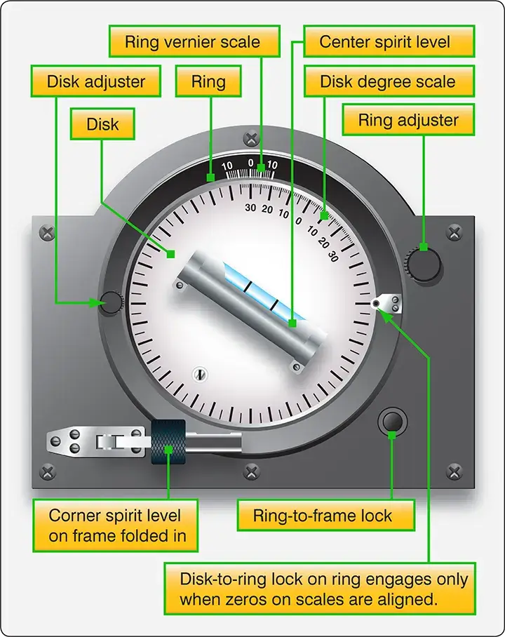
Protractors are tools for measuring angles in degrees. Various types of protractors are used to determine the travel of flight control surfaces. One protractor that can be used to measure aileron, elevator, or wing flap travel is the universal propeller protractor shown in Figure 26.
 |
| Figure 26. Universal propeller protractor |
This protractor is made up of a frame, disc, ring, and two spirit levels. The disc and ring turn independently of each other and of the frame. (The center spirit level is used to position the frame vertically when measuring propeller blade angle.) The center spirit level is used to position the disc when measuring control surface travel. A disc-to-ring lock is provided to secure the disc and ring together when the zero on the ring vernier scale and the zero on the disc degree scale align. The ring-to-frame lock prevents the ring from moving when the disc is moved. Note that they start at the same point and advance in opposite directions. A double 10-part vernier is marked on the ring.
The rigging of the trim tab systems is performed in a similar manner. The trim tab control is set to the neutral (no trim) position, and the surface tab is usually adjusted to streamline with the control surface. However, on some aircraft, the specifications may require that the trim tabs be offset a degree or two from streamline when in the neutral position. After the tab and tab control are in the neutral position, adjust the control cable tension.
Pins, usually called rig pins, are sometimes used to simplify the setting of pulleys, levers, bellcranks, etc., in their neutral positions. A rig pin is a small metallic pin or clip. When rig pins are not provided, the neutral positions can be established by means of alignment marks, by special templates, or by taking linear measurements.
If the final alignment and adjustment of a system are correct, it should be possible to withdraw the rigging pins easily. Any undue tightness of the pins in the rigging holes indicates incorrect tensioning or misalignment of the system.
After a system has been adjusted, the full and synchronized movement of the controls should be checked. When checking the range of movement of the control surface, the controls must be operated from the flight deck and not by moving the control surfaces. During the checking of control surface travel, ensure that chains, cables, etc., have not reached the limit of their travel when the controls are against their respective stops.
Adjustable and nonadjustable stops (whichever the case requires) are used to limit the throw-range or travel movement of the ailerons, elevator, and rudder. Usually there are two sets of stops for each of the three main control surfaces. One set is located at the control surface, either in the snubber cylinders or as structural stops; the other, at the flight deck control. Either of these may serve as the actual limit stop.
However, those situated at the control surface usually perform this function. The other stops do not normally contact each other, but are adjusted to a definite clearance when the control surface is at the full extent of its travel. These work as override stops to prevent stretching of cables and damage to the control system during violent maneuvers. When rigging control systems, refer to the applicable maintenance manual for the sequence of steps for adjusting these stops to limit the control surface travel.
Where dual controls are installed, they must be synchronized and function satisfactorily when operated from both positions.
Trim tabs and other tabs should be checked in a manner similar to the main control surfaces. The tab position indicator must be checked to see that it functions correctly. If jackscrews are used to actuate the trim tab, check to see that they are not extended beyond the specified limits when the tab is in its extreme positions.
After determining that the control system functions properly and is correctly rigged, it should be thoroughly inspected to determine that the system is correctly assembled and operates freely over the specified range of movement.
Checking and Safetying the System
Whenever rigging is performed on any aircraft, it is good practice to have a second set of eyes inspect the control system to make certain that all turnbuckles, rod ends, and attaching nuts and bolts are correctly safetied.
As a general rule, all fasteners on an aircraft are safetied in some manner. Safetying is defined as securing by various means any nut, bolt, turnbuckle, etc., on the aircraft so that vibration does not cause it to loosen during operation.
Most aircraft manufacturers have a Standard Practices section in their maintenance manuals. These are the methods that should be used when working on a particular system of a specific aircraft. However, most standard aircraft hardware has a standard method of being safetied. The following information provides some of the most common methods used in aircraft safetying.
The most commonly used safety wire method is the double-twist, utilizing stainless steel or Monel wire in the .032 to .040-inch diameter range. This method is used on studs, cable turnbuckles, flight controls, and engine accessory attaching bolts. A single-wire method is used on smaller screws, bolts, and/or nuts when they are located in a closely spaced or closed geometrical pattern. The single-wire method is also used on electrical components and in places that are difficult to reach. [Figure 27]
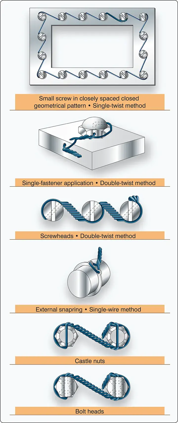 |
| Figure 27. Double-wrap and single safety wire methods for nuts, bolts, and snap rings |
Safety-of-flight emergency equipment, such as portable fire extinguishers, oxygen regulators, emergency valves, firewall shut-offs, and seals on first-aid kits, are safetied using a single copper wire (.020-inch diameter) or aluminum wire (.031-inch diameter). The wire on this emergency equipment is installed only to indicate the component is sealed or has not been actuated. It must be possible to break the wire seal by hand, without the use of any tools.
The use of safety wire pliers, or wire twisters, makes the job of safetying much easier on the mechanic’s hands and produces a better finished product. [Figure 28]
 |
| Figure 28. Use of safety-wire pliers or wire twisters |
The wire should have six to eight twists per inch of wire and be pulled taut while being installed. Where practicable, install the safety wire around the head of the fastener and twist it in such a manner that the loop of the wire is pulled close to the contour of the unit being safety wired, and in the direction that would have the tendency to tighten the fastener. [Figure 29]
 |
| Figure 29. Examples of various fasteners and methods of safetying |
Cotter pins are used to secure such items as bolts, screws, pins, and shafts. They are used at any location where a turning or actuating movement takes place. The diameter of the cotter pin selected for any application should be the largest size that will fit consistent with the diameter of the cotter pin hole and/or the slots in the castellated nut. Cotter pins, like safety wire, should never be re-used on aircraft. [Figure 30]
 |
| Figure 30. Securing hardware with cotter pins |
Self-locking nuts are used in applications where they are not removed often. There are two types of self-locking nuts currently in use. One is all metal and the other has an insert, usually of fiber or nylon.
It is extremely important that the manufacturer’s Illustrated Parts Book (IPB) be consulted for the correct type and grade of lock nut for various locations on the aircraft. The finish or plating color of the nut identifies the type of application and environment in which it can be used. For example, a cadmium-plated nut is gold in color and provides exceptionally good protection against corrosion, but should not be used in applications where the temperature may exceed 450 °F.
Repeated removal and installation causes the self-locking nut to lose its locking feature. They should be replaced when they are no longer capable of maintaining the minimum prevailing torque. [Figure 31]
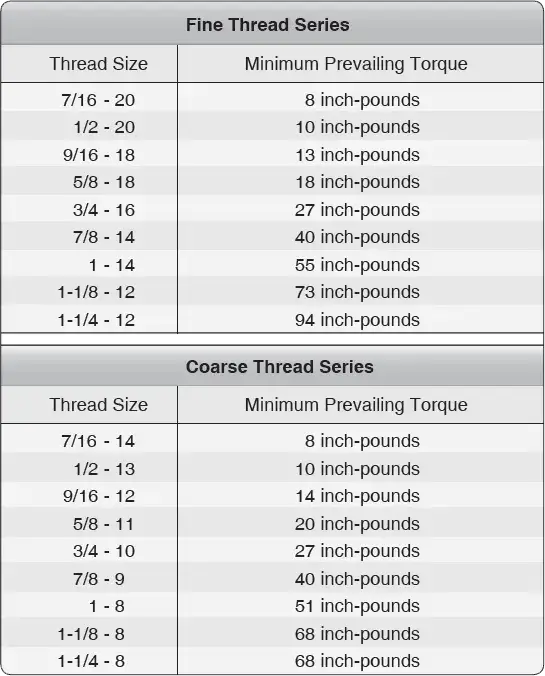 |
| Figure 31. Minimum prevailing torque values for reused self-locking nuts |
Lock washers may be used with bolts and machine screws whenever a self-locking nut or castellated nut is not applicable. They may be of the split washer spring type, or a multi-serrated internal or external star washer.
Pal nuts may be a second nut tightened against the first and used to force the primary nut thread against the bolt or screw thread. They may also be of the type that are made of stamped spring steel and are to be used only once and replaced with new ones when removed.