Repairs to aircraft structures vary depending on the location and extent of the damage. Typical repair methods are applied to major structural components such as skins, stringers, spars, ribs, bulkheads, and other structural members.
When repairing any damaged component or part, always consult the applicable section of the manufacturer’s Structural Repair Manual (SRM) for the aircraft. The SRM normally provides illustrations of similar repairs and specifies the types of materials, rivets, rivet spacing, and the methods and procedures required. Additional information necessary to accomplish the repair is also included.
If the required information cannot be found in the SRM, a similar repair or assembly originally installed by the aircraft manufacturer should be used as a reference.
Floats
To maintain the float in an airworthy condition, periodic and frequent inspections should be made because of the rapidity of corrosion on metal parts, particularly when the aircraft is operated in salt water. Inspection of floats and hulls involves examination for damage due to corrosion, collision with other objects, hard landings, and other conditions that may lead to failure.
Sheet-metal floats should be repaired using approved practices; however, the seams between sections of sheet metal should be waterproofed with suitable fabric and sealing compound. A float that has undergone hull repairs should be tested by filling it with water and allowing it to stand for at least 24 hours to see if any leaks develop. [Figure 1]
 |
| Figure 1. Float repair |
Corrugated Skin Repair
Some of the flight controls of smaller general aviation aircraft have beads in their skin panels. The beads give some stiffness to the thin skin panels. The beads for the repair patch can be formed with a rotary former or press brake. [Figure 2]
 |
| Figure 2. Beaded skin repair on corrugated surfaces |
Replacement of a Panel
Damage to metal aircraft skin that exceeds repairable limits requires replacement of the entire panel. [Figure 3] A panel must also be replaced when there are too many previous repairs in a given section or area.
 |
| Figure 3. Replacement of an entire panel |
In aircraft construction, a panel is any single sheet of metal covering. A panel section is the part of a panel between adjacent stringers and bulkheads. Where a section of skin is damaged to such an extent that it is impossible to install a standard skin repair, a special type of repair is necessary. The particular type of repair required depends on whether the damage is repairable outside the member, inside the member, or to the edges of the panel.
Outside the Member
For damage that, after being trimmed, has 81⁄2 rivet diameters or more of material, extend the patch to include the manufacturer’s row of rivets and add an extra row inside the members.
Inside the Member
For damage that, after being trimmed, has less than 81⁄2 manufacturer’s rivet diameters of material inside the members, use a patch that extends over the members and an extra row of rivets along the outside of the members.
Edges of the Panel
For damage that extends to the edge of a panel, use only one row of rivets along the panel edge, unless the manufacturer used more than one row. The repair procedure for the other edges of the damage follows the previously explained methods.
The procedures for making all three types of panel repairs are similar. Trim out the damaged portion to the allowances mentioned in the preceding paragraphs. For relief of stresses at the corners of the trim-out, round them to a minimum radius of ½-inch. Lay out the new rivet row with a transverse pitch of approximately five rivet diameters and stagger the rivets with those put in by the manufacturer. Cut the patch plate from material of the same thickness as the original or the next greater thickness, allowing an edge distance of 21⁄2 rivet diameters. At the corners, strike arcs having the radius equal to the edge distance.
Chamfer the edges of the patch plate for a 45° angle and form the plate to fit the contour of the original structure. Turn the edges downward slightly so that the edges fit closely. Place the patch plate in its correct position, drill one rivet hole, and temporarily fasten the plate in place with a fastener. Using a hole finder, locate the position of a second hole, drill it, and insert a second fastener.
Then, from the back side and through the original holes, locate and drill the remaining holes. Remove the burrs from the rivet holes and apply corrosion protective material to the contacting surfaces before riveting the patch into place.
Repair of Lightening Holes
As discussed earlier, lightening holes are cut in rib sections, fuselage frames, and other structural parts to reduce the weight of the part. The holes are flanged to make the web stiffer. Cracks can develop around flanged lightening holes, and these cracks need to be repaired with a repair plate. The damaged area (crack) needs to be stop drilled or the damage must be removed.
The repair plate is made of the same material and thickness as the damaged part. Rivets are the same as in surrounding structure and the minimum edge distance is 2 times the diameter and spacing is between four to six times the diameter. Figure 4 illustrates a typical lightening hole repair.
 |
| Figure 4. Repair of lightening holes |
Repairs to a Pressurized Area
The skin of aircraft that are pressurized during flight is highly stressed. The pressurization cycles apply loads to the skin, and the repairs to this type of structure require more rivets than a repair to a non-pressurized skin. [Figure 5]
 |
| Figure 5. Pressurized skin repair |
- Remove the damaged skin section.
- Radius all corners to 0.5-inch.
- Fabricate a doubler of the same type of material as, but of one size greater thickness than, the skin. The size of the doubler depends on the number of rows, edge distance, and rivet spacing.
- Fabricate an insert of the same material and same thickness as the damaged skin. The skin to insert clearance is typically 0.015-inch to 0.035-inch.
- Drill the holes through the doubler, insert, and original skin.
- Spread a thin layer of sealant on the doubler and secure the doubler to the skin with Clecos.
- Use the same type of fastener as in the surrounding area, and install the doubler to the skin and the insert to the doubler. Dip all fasteners in the sealant before installation.
Stringer Repair
The fuselage stringers extend from the nose of the aircraft to the tail, and the wing stringers extend from the fuselage to the wing tip. Surface control stringers usually extend the length of the control surface. The skin of the fuselage, wing, or control surface is riveted to stringers.
Stringers may be damaged by vibration, corrosion, or collision. Because stringers are made in many different shapes, repair procedures differ. The repair may require the use of preformed or extruded repair material, or it may require material formed by the airframe technician. Some repairs may need both kinds of repair material. When repairing a stringer, first determine the extent of the damage and remove the rivets from the surrounding area. [Figure 6]
 |
| Figure 6. Stringer repair |
Then, remove the damaged area by using a hacksaw, keyhole saw, drill, or file. In most cases, a stringer repair requires the use of an insert and a splice angle. When locating the splice angle on the stringer during repair, be sure to consult the applicable structural repair manual for the repair piece’s position. Some stringers are repaired by placing the splice angle on the inside, whereas others are repaired by placing it on the outside.
Extrusions and preformed materials are commonly used to repair angles and inserts or fillers. If repair angles and fillers must be formed from flat sheet stock, use the brake. It may be necessary to use bend allowance and sight lines when making the layout and bends for these formed parts. For repairs to curved stringers, make the repair parts so that they fit the original contour.
Figure 7 shows a stringer repair by patching. This repair is permissible when the damage does not exceed two-thirds of the width of one leg and is not more than 12 inches long. Damage exceeding these limits can be repaired by one of the following methods.
 |
| Figure 7. Stringer repair by patching |
Figure 8 illustrates repair by insert where damage exceeds two-thirds of the width of one leg and after a portion of the stringer is removed.
 |
| Figure 8. Stringer repair by insertion when damage exceeds two-thirds of one leg in width |
Figure 9 shows repair by insert when the damage affects only one stringer and exceeds 12 inches in length.
 |
| Figure 9. Stringer repair by insertion when damage affects only one stringer |
Figure 10 illustrates repair by an insertion when damage affects more than one stringer.
 |
| Figure 10. Stringer repair by insertion when damage affects more than one stringer |
Former or Bulkhead Repair
Bulkheads are the oval-shaped members of the fuselage that give form to and maintain the shape of the structure. Bulkheads or formers are often called forming rings, body frames, circumferential rings, belt frames, and other similar names. They are designed to carry concentrated stressed loads.
There are various types of bulkheads. The most common type is a curved channel formed from sheet stock with stiffeners added. Others have a web made from sheet stock with extruded angles riveted in place as stiffeners and flanges. Most of these members are made from aluminum alloy. Corrosion-resistant steel formers are used in areas that are exposed to high temperatures.
Bulkhead damages are classified in the same manner as other damages. Specifications for each type of damage are established by the manufacturer and specific information is given in the maintenance manual or SRM for the aircraft. Bulkheads are identified with station numbers that are very helpful in locating repair information. Figure 11 is an example of a typical repair for a former, frame section, or bulkhead repair.
 |
| Figure 11. Bulkhead repair |
- Stop drill the crack ends with a No. 40 size drill.
- Fabricate a doubler of the same material but one size thicker than the part being repaired. The doubler should be of a size large enough to accommodate 1⁄8inch rivet holes spaced one inch apart, with a minimum edge distance of 0.30-inch and 0.50-inch spacing between staggered rows. [Figure 12]
- Attach the doubler to the part with clamps and drill holes.
- Install rivets.
 |
| Figure 12. Wing spar repair |
Most repairs to bulkheads are made from flat sheet stock if spare parts are not available. When fabricating the repair from flat sheet, remember the substitute material must provide cross-sectional tensile, compressive, shear, and bearing strength equal to the original material. Never substitute material that is thinner or has a cross-sectional area less than the original material. Curved repair parts made from flat sheet must be in the “0” condition before forming, and then must be heat treated before installation.
Longeron Repair
Generally, longerons are comparatively heavy members that serve approximately the same function as stringers. Consequently, longeron repair is similar to stringer repair. Because the longeron is a heavy member and more strength is needed than with a stringer, heavy rivets are used in the repair. Sometimes bolts are used to install a longeron repair due to the need for greater accuracy; however, they are not as suitable as rivets. Also, bolts require more time for installation.
If the longeron consists of a formed section and an extruded angle section, consider each section separately. A longeron repair is similar to a stringer repair, but keep the rivet pitch between 4 and 6 rivet diameters. If bolts are used, drill the bolt holes for a light drive fit.
Spar Repair
The spar is the main supporting member of the wing. Other components may also have supporting members called spars that serve the same function as the spar does in the wing. Spars serve as the primary structural members of the section in which they are located, even though they are not in the center.
The spar is usually the first member located during the construction of the section, and the other components are fastened directly or indirectly to it. Because of the load the spar carries, it is very important that particular care be taken when repairing this member to ensure the original strength of the structure is not impaired. The spar is constructed so that two general classes of repairs, web repairs and cap strip repairs, are usually necessary.
Figures 13 and 14 are examples of typical spar repairs.
 |
| Figure 13. Wing spar repair |
 |
| Figure 14. Wing spar repair |
The damage to the spar web can be repaired with a round or rectangular doubler. Damage smaller than 1 inch is typically repaired with a round doubler and larger damage is repaired with a rectangular doubler.
- Remove the damage and radius all corners to 0.5-inch.
- Fabricate doubler; use the same material and thickness. The doubler size depends on edge distance (minimum of 2D) and rivet spacing (4-6D).
- Drill through the doubler and the original skin and secure the doubler with Clecos.
- Install rivets.
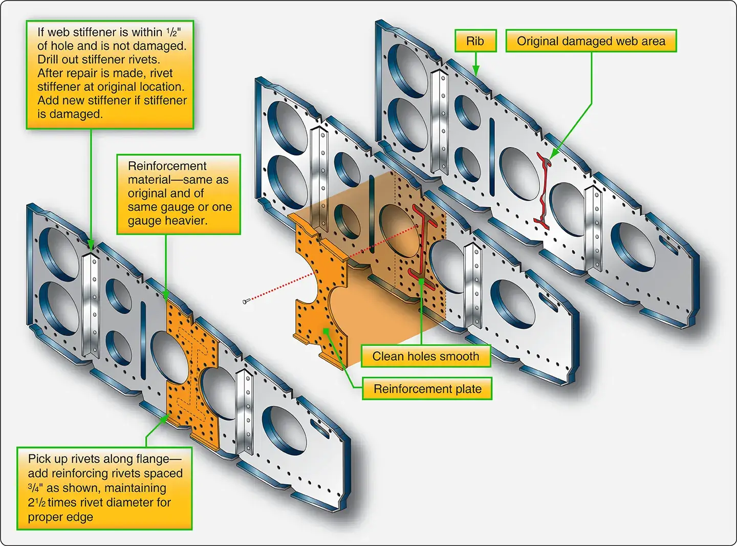
Rib and Web Repair
Web repairs can be classified into two types:
- Those made to web sections considered critical, such as those in the wing ribs.
- Those considered less critical, such as those in elevators, rudders, flaps, and the like.
Web sections must be repaired in such a way that the original strength of the member is restored. In the construction of a member using a web, the web member is usually a light gauge aluminum alloy sheet forming the principal depth of the member. The web is bounded by heavy aluminum alloy extrusions known as cap strips. These extrusions carry the loads caused by bending and also provide a foundation for attaching the skin. The web may be stiffened by stamped beads, formed angles, or extruded sections riveted at regular intervals along the web.
The stamped beads are a part of the web itself and are stamped in when the web is made. Stiffeners help to withstand the compressive loads exerted upon the critically stressed web members. Often, ribs are formed by stamping the entire piece from sheet stock. That is, the rib lacks a cap strip, but does have a flange around the entire piece, plus lightening holes in the web of the rib. Ribs may be formed with stamped beads for stiffeners, or they may have extruded angles riveted on the web for stiffeners.
Most damages involve two or more members, but only one member may be damaged and need repairing. Generally, if the web is damaged, cleaning out the damaged area and installing a patch plate are all that is required.
The patch plate should be of sufficient size to ensure room for at least two rows of rivets around the perimeter of the damage that includes proper edge distance, pitch, and transverse pitch for the rivets. The patch plate should be of material having the same thickness and composition as the original member. If any forming is necessary when making the patch plate, such as fitting the contour of a lightening hole, use material in the “0” condition and then heat treat it after forming.
Damage to ribs and webs that requires a repair larger than a simple plate probably needs a patch plate, splice plates, or angles and an insertion. [Figure 15]
 |
| Figure 15. Wing rib repair |
Leading Edge Repair
The leading edge is the front section of a wing, stabilizer, or other airfoil. The purpose of the leading edge is to streamline the forward portion of the wing or control surface to ensure effective airflow. The space within the leading edge is sometimes used to store fuel. This space may also house extra equipment, such as landing lights, plumbing lines, or thermal anti-icing systems.
The construction of the leading edge section varies with the type of aircraft. Generally, it consists of cap strips, nose ribs, stringers, and skin. The cap strips are the main lengthwise extrusions, and they stiffen the leading edges and furnish a base for the nose ribs and skin. They also fasten the leading edge to the front spar.
The nose ribs are stamped from aluminum alloy sheet or machined parts. These ribs are U-shaped and may have their web sections stiffened. Regardless of their design, their purpose is to give contour to the leading edge. Stiffeners are used to stiffen the leading edge and supply a base for fastening the nose skin. When fastening the nose skin, use only flush rivets.
Leading edges constructed with thermal anti-icing systems consist of two layers of skin separated by a thin air space. The inner skin, sometimes corrugated for strength, is perforated to conduct the hot air to the nose skin for anti-icing purposes.
Damage can be caused by contact with other objects, namely, pebbles, birds, and hail. However, the major cause of damage is carelessness while the aircraft is on the ground.
A damaged leading edge usually involves several structural parts. FOD damage probably involves the nose skin, nose ribs, stringers, and possibly the cap strip. Damage involving all of these members necessitates installing an access door to make the repair possible.
First, the damaged area has to be removed and repair procedures established. The repair requires inserts and splice pieces. If the damage is serious enough, it may require repair of the cap strip and stringer, a new nose rib, and a skin panel. When repairing a leading edge, follow the procedures prescribed in the appropriate repair manual for this type of repair. [Figure 16]
 |
| Figure 16. Leading edge repair |
Repairs to leading edges are more difficult to accomplish than repairs to flat and straight structures because the repair parts need to be formed to fit the existing structure.
Trailing Edge Repair
A trailing edge is the rear-most part of an airfoil found on the wings, ailerons, rudders, elevators, and stabilizers. It is usually a metal strip that forms the shape of the edge by tying the ends of a rib section together and joining the upper and lower skins. Trailing edges are not structural members, but they are considered to be highly stressed in all cases.
Damage to a trailing edge may be limited to one point or extended over the entire length between two or more rib sections. Besides damage resulting from collision and careless handling, corrosion damage is often present. Trailing edges are particularly subject to corrosion because moisture collects or is trapped in them.
Thoroughly inspect the damaged area before starting repairs, and determine the extent of damage, the type of repair required, and the manner in which the repair should be performed. When making trailing edge repairs, remember that the repaired area must have the same contour and be made of material with the same composition and temper as the original section. The repair must also be made to retain the design characteristics of the airfoil. [Figure 17]
 |
| Figure 17. Trailing edge repair |
Specialized Repairs
Figures 18 through 22 are examples of repairs for various structural members.
 |
| Figure 18. C-channel repair |
 |
| Figure 19. Primary Z-section repair |
 |
| Figure 20. U-channel repair |
 |
| Figure 21. Channel repair by patching |
 |
| Figure 22. Channel repair by insertion |
Specific dimensions are not included since the illustrations are intended to present the basic design philosophy of general repairs rather than be used as repair guidelines for actual structures. Remember to consult the SRM for specific aircraft to obtain the maximum allowable damage that may be repaired and the suggested method for accomplishing the repair.
Inspection Openings
If it is permitted by the applicable aircraft maintenance manual, installation of a flush access door for inspection purposes sometimes makes it easier to repair the internal structure as well as damage to the skin in certain areas. This installation consists of a doubler and a stressed cover plate.
A single row of nut plates is riveted to the doubler, and the doubler is riveted to the skin with two staggered rows of rivets. [Figure 23] The cover plate is then attached to the doubler with machine screws.
 |
| Figure 23. Inspection hole |
Frequently Asked Questions
What unique post-repair testing and fastener restrictions apply to sheet-metal floats?
How do rivet layouts change when splicing sheet metal inside versus outside a structural member?
- Outside the Member: If 8.5 rivet diameters ($8.5D$) or more of material remains, you extend the patch plate to capture the manufacturer's original rivet row and add one extra row inside the structural members.
- Inside the Member: If less than $8.5D$ of material remains, the repair patch must extend completely over the structural members, and an extra row of fasteners is driven along the outside of the members.
Why do repairs in cabin pressurized zones require distinct installation steps?
What are the limits for patching a damaged stringer before an insert is required?
RELATED POSTS