Turbine engine discrepancies can be either obvious or hidden. Hidden problems, when not detected and corrected, often cause major problems with continued engine operations. Hidden troubles are detected by continuously monitoring engine operating parameters, comparing them over time to detect subtle changes that indicate wear and transient problems. By analyzing engine trends and consulting the airframe and engine manufacturer's troubleshooting information, you can systematically isolate and correct defects before they cause major problems.
Trend Monitoring
One of the most useful procedures used to detect hidden and subtle problems with turbine engines is to perform continuous evaluations of engine performance parameters over time. A properly operating turbine engine produces fairly predictable and consistent compressor rpm, exhaust gas temperature , fuel flow, and power output for a given ambient pressure altitude and temperature. By recording parameter data during each flight, and analyzing changes when they occur, problems can often be detected and corrected early in their development.Performance monitoring of engines, commonly referred to as trend monitoring, is a technique used by aviation maintenance organizations and engine manufacturers to improve engine service life and reduce operating costs. The monitoring of an engine's performance and condition over a period of time provides a database for trend analysis. Trend analysis alerts an operator to deteriorating performance, providing an opportunity to take corrective action before substantial engine damage or failure occurs.
Proper trend monitoring begins when an engine is new or recently overhauled. Data collected during the initial operations establishes a baseline to compare to all subsequent operations data. After establishing an initial relationship between performance parameters, operating data is reviewed at regular intervals. Significant changes in the relationships between performance parameters may signal impending failures.
Data collection methods range from onboard computers to manual entries on paper forms . Regardless of the method used, conditions under which a certain parameter is measured should be consistent to be useful in a trend analysis. For example, EGT measurements and fuel flow indications should always be taken at the same power setting, and under the same ambient conditions. However, since ambient conditions often vary between flights, correction factors must be taken into account with data. If this is not done, it is possible to obtain data which skews the trend analysis and gives false indications of a problem. [Figure 1]
 |
| Figure 1 . On most turbine aircraft, engine operating parameters are recorded by the flight crew during cruise flight |
Since it takes a great deal of experience to identify subtle trend variations, aircraft and engine manufacturers often provide trend monitoring services for their customers. In some cases, second party companies may also provide these services. By using an FAA-approved trend monitoring program, engine operating times between overhaul, or times and cycles between required inspections, may be extended. While trend monitoring improves safety, it also provides tremendous economical incentives.
Trend analysis information can be broken down into two broad categories; performance and mechanical. Typical performance parameters include information on EPR or torquemeter (Np) readings, compressor N1 and N2 speeds, gas generator speed (Ng) , fuel flow (Wf) , and EGT or ITT. On the other hand, mechanical parameters typically include instrument readings for oil pressure, oil temperature, oil quantity, vibration, oil pressure warning lights, and bypass lights. Accurately interpreting a trend analysis requires the ability to discern small shifts in operating parameters on one or more gauges and to accurately compare the information to base line data. [Figure 2)
 |
| Figure 2. Engine data collected over a period of time is plotted on a graph. By observing deviations from established parameters, hidden problems may be detected |
Spectrometric Oil Analysis
Another technique used to detect hidden problems in turbine engines is done by performing a spectrometric oil analysis. A spectrometric oil analysis program, or SOAP, is available to aircraft operators to help detect developing problems in an engine. Spectrometric analysis for metal particles suspended in oil is possible because metallic ions emit characteristic light spectra when vaporized by an electric arc. Each metal produces a unique spectrum, allowing easy identification of the metals present in an oil sample. The wavelength of spectral lines identifies each metal and the intensity of the line is used to measure the quantity of that metal in a sample.
When participating in a spectrometric oil analysis program, periodic samples of oil are taken from the engine after shutdown or prior to servicing. Samples are taken from a sediment free location in the main oil tank and sent to an oil analysis laboratory. In the lab, a film of the used oil sample is picked up on the rim of a rotating, high purity, graphite disk electrode. A precisely controlled, high voltage, AC spark is discharged from a vertical electrode to the rotating disk. When this occurs, the film of oil on the disk begins to burn. Light emitted by the burning oil passes through a series of slits, precisely positioned to detect the wavelengths of various metals. As light passes through the slit, photo multiplier tubes electronically convert the light waves into energy, which automatically prints the analytical results on the laboratory record sheets. The wear metals present are so small that they flow freely through an engine's system filters. The spectrometric therefore measures the particles that move in suspension in the oil and are too small to appear on either the oil screen or chip detector. [Figure 3]
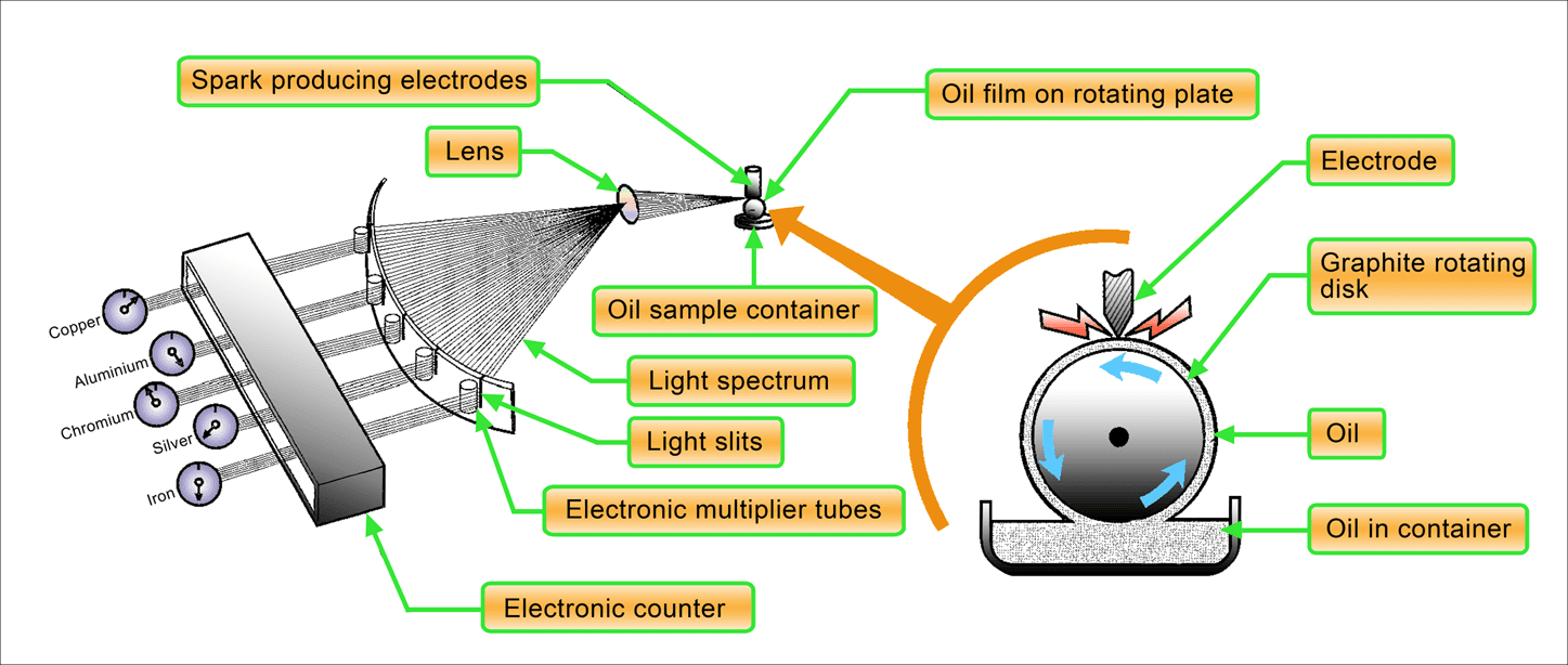 |
| Figure 3. In spectrometric oil testing, the used oil sample is applied to a rotating, graphite disk and ignited by a high voltage, AC spark |
Alloyed metals in turbine engines may contain amounts of aluminum, iron, chromium, silver, copper, tin, magnesium, lead, nickel, or titanium. Silver is accurately measured in concentrations down to one-half part silver in one million parts of oil. Most other metals are measured accurately in concentrations down to two or three parts per million. The maximum amount of normal wear has been determined for each metal of the particular system in the program. This amount is called its threshold limit of contamination and is measured by weight in parts per million (PPM). If after interpreting the results, the lab identifies a sharp increase of abnormal concentrations of metal, the lab will immediately notify you.
The types of metals identified during a spectrometric oil analysis provide invaluable information to help you determine the source of the contamination. Engine manufacturers provide a list of engine components and the materials used in their construction. Consult this information to identify areas where to begin troubleshooting and for corrective actions to take when the source of contamination has been identified.
Troubleshooting Resources
Instructions for troubleshooting gas turbine powerplants are contained in the aircraft and engine manufacturer's maintenance manuals. The information contained in the airframe manual provides operational considerations in relation to the airframe systems and general powerplant troubleshooting guidance. For additional, and often more specific engine troubleshooting information, consult the powerplant manufacturer's manuals.
Standard engine instrument readings are used with troubleshooting guides to provide clues as to the cause of a given engine malfunction. In addition, some aircraft are equipped with built-in test equipment, or BITE test systems. BITE systems consist of sensors, transducers, and computer monitoring devices, which detect and record engine data such as vibration levels, temperatures, and pressures. A typical BITE test requires you to make entries on a keypad in the cockpit or at a remote terminal in order to receive engine data. However, even this sophisticated equipment can only provide you with the symptoms of a problem, leaving you to determine the actual problem.
A typical turbine engine maintenance manual provides one or more troubleshooting tables or flow diagram charts to aid in pinpointing the cause of common malfunctions. However, it is not possible for these to identify all malfunctions. Instead, troubleshooting tables and flow charts provide you with a starting point in the troubleshooting process. This, combined with a thorough knowledge of the engine systems, logical reasoning, and experience provides you with the information necessary to diagnose and correct complicated or intermittent malfunctions. See figure 4.
 |
| Figure 4. Turbine engine trouble shooting procedure |
Most powerplant manufacturers group engine troubles into categories similar to the following:
- Starting and shutdown faults
- Operational faults
- Performance faults and engine trend monitoring (ETM) shifts
- Lubrication faults and oil contamination
To isolate a fault, it is necessary to have reports of previous problems and any actions that may have been taken to correct them. You should check the probable source of the trouble, by use of diagnostic tests, until the defect has been isolated. As always, use a systematic sequence to isolate the fault to prevent making wrong and costly assumptions as to the cause of a problem.
Starting and Shutdown Faults
Aside from internal engine problems, inappropriate starting techniques and other problems that are external from the engine may cause starting malfunctions. When attempting to start a turbine engine for maintenance checks, it is advisable to always use auxiliary pneumatic or electric power sources. Insufficient starter power may prevent the engine from achieving proper compressor rotational speeds to support normal combustion. In addition, whenever starting a turbine engine, you should also consider ambient temperature and wind conditions. If the engine and fuel has been cold soaked from exposure to extremely cold outside temperatures, it may not be possible for the fuel to properly atomize to support combustion. In extremely cold climates, consider moving the aircraft into a hangar for preheating.
Strong winds blowing through the exhaust duct of an engine may also impede normal air or gas flow through the engine. If the engine fails to start in high wind conditions, reposition the aircraft and perform a dry motoring run to purge residual fuel from the combustors before attempting another start.
Once you have determined that there is sufficient power for starting and after eliminating all other external factors, begin systematically isolating passible engine problems that may be affecting the start. Typical starting problems caused by engine and engine accessory faults consist of the following:
1. Does the starter motor operate? Audibly confirm that you can hear the starter during the start cycle. If there is no indication of starter operation, check the following:
- Check electrical or pneumatic sources to determine that they are adequate and being delivered to the starter. When cross-bleeding pneumatic air from a secondary source such as an APU or another engine, check the operation and position of all bleed-air and start control valves. For electric starters, check the operation of all starter relays and contactors, and the condition of electrical wires and terminal ends.
2. If the starter operates, does the engine rotate? This may be confirmed with the compressor tachometer (Low pressure compressor or N1 , high pressure compressor or N2 , or gas generator compressor or Ng, as appropriate to the type of engine) or by visually checking for engine rotation.
- If there is no rotation, or if rotation is sluggish, check the starter driveshaft for condition and engagement. Manually attempt to rotate the engine by hand and listen for abnormal scrapping or rubbing sounds. Determine the source of any irregularities.
3. If the engine rotates to an appropriate rpm, but still fails to start, check the following items:
- Inspect the ignition system for proper operation. Igniters produce a loud snapping sound during starting. Glow plug ignition systems can be checked by removing the plugs from the combustor and turning the ignition on to check heating elements. If ignition is not evident, check power supplies or the ignition exciter. Also perform insulation and continuity checks on ignition cables.
- Check the fuel pumps, FCU, and fuel nozzles for proper operation and condition. Inspect all aircraft and engine fuel filters and screens for contamination. Check the fuel control unit and fuel pumps for proper output pressures, and inspect fuel nozzles for cleanliness and flow check as necessary.
- Using a fiberoptic borescope, perform an engine inspection to check for severely damaged internal hot section and compressor components.
4. If the engine starts, but tends to hang up, or is sluggish to accelerate, check the following items:
- Check all pneumatic bleed air reference lines to the fuel control unit (FCU) and other parts of the engine for leakage, or blockage.
- Check starting bleed air valves for proper operation. Often, bleed air valves remain open during the initial part of the start sequence to reduce the load on the compressor, but close at higher rpm before light off. Also ensure that all auxiliary airframe system bleed air valves are properly positioned during the start.
- Check the pressurization and dump valve (P&D or purge valve) for proper operation. After shutdown, the valve should open to allow excess fuel to drain, but should close during the start sequence.
Perform additional checks as required for the specific engine as called for in the manufacturer's troubleshooting procedures.
Operational Faults
Operational faults include items that become apparent during normal operations. Faults may include failure of the engine to accelerate or decelerate properly, compressor surges or stalls, transient over temperature conditions, abnormal vibrations, and others.
Engine indicating systems sometimes erroneously show values that are outside normal operating parameters. You should always verify that the engine indicating systems are calibrated and working properly before beginning to diagnose internal engine faults. A Jetcal Analyzer, as described in Turbine Engine Calibration and Testing post, or similar equipment, should be used to check the integrity of the indicating gauges, transmitters, sensing elements, and wiring harnesses.
Some typical operational faults and actions to take to diagnose them are as follows:
1. During mid to low power operations, if a hooting or huffing sound is emitted:
- Check for excess compressor air leakage through bleed air valves. In some instances, manufacturers may recommend blanking off bleed air outlets to diagnose whether the problem is caused by an engine bleed air problem, or possibly that the problem is leakage in an airframe bleed air (pneumatic) system.
- Check the condition of the compressor inlet, blades, and guide vanes for foreign object damage (FOD) and cleanliness. If the compressor section is found dirty, perform an engine performance recovery wash, in accordance with the manufacturer's instructions. If other damage is discovered, consult the manufacturer's maintenance instructions to determine the extent of field repairs that are allowed or if the engine must be disassembled and repaired in an overhaul facility.
2. Engine rpm is excessively high or too low:
- Check the operation of all engine controls. Check power and fuel cutoff controls for full travel to the stops at the FCU (Also condition lever and propeller controls for turboprop engines).
- Check for hang-up or distortion in any cam linkages.
- Check the adjustment of the FCU especially if changes have been recently made during engine trimming operations.
- If the engine experiences an uncontrolled overspeed, check the FCU driveshaft for engagement and FCU bleed air reference lines for obstructions and leakage.
- Check the FCU for contamination, and if detected, isolate the source and replace the FCU with a new or overhauled unit.
3. The engine is slow to accelerate or surges during power application:
- Check bleed air reference delivery tubes for leakage and obstructions.
- Inspect the compressor for cleanliness and FOD damage. Perform a power recovery wash, as required.
- Check bleed air valves for proper operation and the airframe auxiliary bleed air system for leakage.
- Check the FCU fuel filters and screens for contamination. Check the airframe fuel source for contamination and fuel quality.
- When acceleration controls are installed on the FCU, attempt to make adjustments. If maximum adjustments do not obtain desired results, replace the FCU with a new or overhauled unit.
4. If the engine experiences a transient over temperature during operation (exhaust gas temperature or EGT, turbine inlet temperature or TIT, or interstage turbine temperature or ITT):
- Perform a check of the engine temperature indicating instruments to determine the actual extent of the over temperature condition. Determine the maximum temperature value and the length of time of operation above maximum limits. (Consult the engine manufacturer's maintenance instructions to determine required actions. If the engine is allowed to remain in service, isolate the cause of the fault).
- Check for excessive airframe accessory power loading. For example, excess generator loads or excessive bleed air requirements may cause transient engine over temperatures.
- Perform a fiberoptic borescope inspection of the compressor inlet, blades, and guide vanes. Perform a power recovery wash if the compressor is found dirty or corroded. If corrosion is present, follow the manufacturer's instructions for continued operations.
- Inspect the cornbustors and turbine sections for damage and distortion. Flow check the fuel nozzles and verify their alignment in the fuel manifold upon reinstallation.
5. If excessive vibrations are indicated during normal operation:
- Inspect the engine for loose mounting and the condition of all isolation dampeners.
- For turboprop engines, check the propeller balance and the condition of the power section and gearbox.
- Perform a visual inspection (with fiberoptic borescope, as required) of the compressor and turbine sections for FOD damage.
- Check the bleed air valves for proper operation.
- Inspect the oil filter element or screen for signs of contamination and perform a spectrometric oil analysis.
6. Flame out during normal operation:
- Inspect the airframe fuel system for contamination and delivery pressures.
- Check the engine driven fuel pump and FCU for proper fuel delivery.
- Check the acceleration time of the engine and if outside of specifications inspect the FCU and fuel nozzles for contamination.
- Inspect the compressor and turbine sections for FOD damage.
7. Low power or if all engine indicating parameters are showing low.
- Verify proper operation of the indicating systems.
- Check engine control linkages for proper operation and travel limits.
- Check bleed air reference lines to the FCU and other engine accessories.
- Attempt to perform engine trimming as specified by the engine manufacturer. If unable to achieve desired results, inspect the FCU and fuel nozzles for contamination and proper operation.
8. Unusual noises such as squealing or rubbing heard during operation:
- Rotate the engine by hand to detect unusual rubbing at low rotational speeds. If squealing is only heard at high rpm, inspect the compressor and turbine sections for evidence of blade tip to shroud rubbing.
- Check all engine mounted accessories for proper operation.
- Inspect the engine oil filter element or screen for evidence of contamination and perform a spectrometric oil analysis to check for wear of internal engine parts.
Performance Faults and Engine Trend Monitoring (ETM} Shifts
As previously discussed, most turbine-powered aircraft engine performance is continuously evaluated through a trend monitoring program. By performing a trend analysis, corrective actions can be taken to correct an unsafe condition as soon as the engine's operating parameters deviate from their established baseline.
It is not uncommon for turbine engines to display slight parameter variations and degradation in performance as a factor of normal wear. Significant changes indicate abnormal conditions that must be isolated to assure maximum engine efficiency and safety. Variations in fuel flow (Wf), temperatures, and power (N1 , EPR or torquemeter Np) are the primary parameters used to evaluate the engine's performance, but other parameters such as oil pressure and chip detector warning systems are also used to indicate mechanical irregularities.
Common performance faults include the following symptoms along with their possible causes:
1. Rapid shift in engine temperature monitoring parameter that is not accompanied by shifts in fuel flow, compressor speed, or power output:
- An indicator or sensing system fault almost always causes rapid temperature shifts without other parameters being affected. Check the condition and operation of temperature probes and bus bars. Perform an operational check of the temperature sensing system using a Jetcal Analyzer, or similar calibration equipment.
- For multi-engine aircraft, when both engines have a similar rapid temperature shift, check the airframe outside air temperature (OAT) system, and altitude or airspeed indicating systems since malfunctions may cause erroneous data reports from the flight crew.
- A slight shift of engine temperature parameters without other accompanying parameter shifts may indicate fuel nozzle contamination. Remove the fuel nozzles for flow checks and verify nozzle alignment in the fuel manifold upon reinstallation.
2. Changes in a single operating parameter without corresponding changes to other operating parameters, or changes to all operating parameters in a proportionate amount.
- Again, if fuel flow shows a rapid change without an engine temperature or compressor speed change, this is usually indicative of an instrument system fault. Perform a Jetcal analysis to check each instrument indicating system.
- If all parameters indicate a decrease in a proportionate amount, it often indicates that the engine power sensing, or airframe OAT, airspeed, or pressure altitude instruments are at fault. For example, if the EPR or torquemeter is in error, the flight crew will set power in accordance with the erroneous indication. This will always be reflected in changes to all other operating parameters in proportionate amounts.
3. Exhaust temperature, compressor speed, and fuel flow all show an increase beyond baseline when desired power settings are established:
- Perform a calibration check of all engine instruments and indicating systems.
- Check for engine inlet obstructions, distortion, and FOD damage to the compressor.
- Perform a power recovery wash if the compressor is found dirty or corroded. However, this is generally not considered to be the fault when sudden parameter shifts occur, but may be useful to partially regain performance losses.
- Check the operation and condition of all bleed air valves and airframe auxiliary bleed air systems. Airframe systems can be isolated from the engine by the installation of blanking plates, as previously discussed.
- Check for any seal damage or other sources of hot air being ingested back into the engine intake. For ground operations, this may be caused by the use of reverse thrust or by high winds blowing into the tailpipe or carrying hot exhaust gases toward the engine intake.
- Determine if any hot starts may have been recently encountered, which may explain the rapid parameter shift. If evidence suggests that a hot start may have been encountered, perform a hot section inspection to determine the engine's internal component integrity. Consult the engine manufacturer's hot start inspection procedures and over temperature limitations.
4. Engine temperature and fuel flow increase while compressor speeds decrease or remain unchanged:
- Inspect the turbine section for damage to exhaust nozzles, turbine blades and turbine disk.
- Check the pressurization and dump valve (purge valve) for proper operation.
- Check for bleed air leakage and for proper bleed air valve operation.
- Inspect the compressor section for damage and cleanliness. Perform a power recovery wash if the compressor is found dirty or corroded.
Lubrication Faults and Oil Contamination
Mechanical faults are sometimes detected by performance monitoring systems including oil pressure gauges, oil temperature gauges, metallic chip detectors, and other components. In addition, internal engine faults are detected during oil filter inspections and spectrometric oil analysis of oil samples. Typical lubrication system faults and oil contamination considerations include the following:
1. Low oil pressure indications:
- Insufficient oil quantity. Follow the engine manufacturer's instructions for checking the oil level. In most cases, the oil level must be checked within a specified time after the engine has been operated.
- Check the indicating system to verify proper pressure gauge indications.
- Check the oil filter and screens for obvious signs of contamination or debris.
- Inspect external components of the lubrication system such as oil to fuel heat exchangers for signs of leakage.
- Inspect the oil pressure relief valve for proper functioning and attempt to adjust the oil pressure to specified levels.
2. High oil pressure indications:
- Check the oil pressure indicating system for proper operation.
- Check the oil pressure relief valve for proper operation and attempt to adjust the valve to achieve specified limits.
3. Fluctuating oil pressure:
- Check the oil level. Insufficient or excessive oil quantity may cause fluctuating oil pressures.
- Check the oil pressure indicating system for proper operation.
- Check the airframe oil cooler system for leaks or blockage.
- Inspect and clean the oil filter and screens, as required.
4. High or low oil temperature indications:
- Check the oil level. Low quantities cause elevated lubrication system operating temperatures.
- Check the oil temperature indicating system for proper operation.
- Inspect the oil cooler for signs of leakage and proper thermostatically controlled bypass valve operations.
- Check the operation of the oil pressure relief valve.
5. Evidence of oil in the tailpipe or exhaust duct;
- Consult the engine manufacturer's troubleshooting instructions to isolate possible internal engine carbon or labyrinth seal failure.
6. Excessive oil consumption:
- Check for leakage or blockage in the pressure and scavenge oil tubes and ports. Leaking scavenge and pressure ports and tubes may also cause fluctuating oil pressures or total loss of oil pressure due to the lubrication pump(s) losing their prime.
- Check for oil leaks in the oil filter element housing, the fuel heater, and the airframe oil cooler assembly.
- Inspect the tailpipe and around case seals for signs of oil. If leakage is evident, refer to the engine manufacturer's instructions for further guidance to isolate the source of the leak.
7. Metallic chip detector warnings:
- Perform an operational check of the chip detector by removing the sensing element. Once removed, inspect for metallic particles between the sensing elements. If the detector is found clean, repair or replace the detector.
- If metallic particles are found, refer to the engine manufacturer's troubleshooting procedures and maintenance manual for information on how to detect the type of metal and probable sources.
8. Evidence of metallic particles in the engine oil and/ or filter:
- Perform a spectrometric oil analysis to determine the exact type of metal and quantity. Compare the results of the analysis to the engine manufacturer's guidance material to determine if the engine can continue in service, and the conditions that must be met for continued service, or if the engine must be removed for disassembly and repair.
RELATED POSTS