In the early stages of aircraft development, relatively low powered reciprocating engines were started by pulling the propeller through a part of a revolution by hand. Difficulty was often experienced in cold weather starting when lubricating oil temperatures were near the congealing point. In addition, the magneto systems delivered a weak starting spark at the very low cranking speeds. This was often compensated for by providing a hot spark using such ignition system devices as the booster coil, induction vibrator, or impulse coupling.
Some small, low-powered aircraft which use hand cranking of the propeller, or propping, for starting are still being operated. Throughout the development of the aircraft reciprocating engine from the earliest use of starting systems to the present, a number of different starter systems have been used. Most reciprocating engine starters are the direct cranking electric type. A few older model aircraft are still equipped with inertia starters. Thus, only a brief description of these starting systems is included in this page.
Inertia Starters
There are three general types of inertia starters: hand, electric, and combination hand and electric. The operation of all types of inertia starters depends on the kinetic energy stored in a rapidly rotating flywheel for cranking ability. Kinetic energy is energy possessed by a body by virtue of its state of motion, which may be movement along a line or spinning action.
In the inertia starter, energy is stored slowly during an energizing process by a manual hand crank or electrically with a small motor. The flywheel and movable gears of a combination hand electric inertia starter are shown in Figure 1. The electrical circuit for an electric inertia starter is shown in Figure 2. During the energizing of the starter, all movable parts within it, including the flywheel, are set in motion. After the starter has been fully energized, it is engaged to the crankshaft of the engine by a cable pulled manually or by a meshing solenoid that is energized electrically. When the starter is engaged, or meshed, flywheel energy is transferred to the engine through sets of reduction gears and a torque overload release clutch. [Figure 3]
 |
| Figure 1. Combination hand and electric inertia starter |
 |
| Figure 2. Electric inertia starting circuit |
 |
| Figure 3. Torque overload release clutch |
Direct Cranking Electric Starter
The most widely used starting system on all types of reciprocating engines utilizes the direct cranking electric starter. This type of starter provides instant and continual cranking when energized. The direct cranking electric starter consists basically of an electric motor, reduction gears, and an automatic engaging and disengaging mechanism that is operated through an adjustable torque overload release clutch. A typical circuit for a direct cranking electric starter is shown in Figure 4. The engine is cranked directly when the starter solenoid is closed. As shown in Figure 4, the main cables leading from the starter to the battery are heavy duty to carry the high current flow, which may be in a range from as high as 350 amperes to 100 amperes (amps), depending on the starting torque required. The use of solenoids and heavy wiring with a remote control switch reduces overall cable weight and total circuit voltage drop.
 |
| Figure 4. Typical starting circuit using a direct cranking electric starter |
The typical starter motor is a 12- or 24-volt, series-wound motor that develops high starting torque. The torque of the motor is transmitted through reduction gears to the overload release clutch. Typically, this action actuates a helically splined shaft moving the starter jaw outward to engage the engine cranking jaw before the starter jaw begins to rotate. After the engine reaches a predetermined speed, the starter automatically disengages. The schematic in Figure 5 provides a pictorial arrangement of an entire starting system for a light twin-engine aircraft.
 |
| Figure 5. Engine starting schematic for a light twin-engine aircraft |
Direct Cranking Electric Starting System for Large Reciprocating Engines
In a typical high horsepower reciprocating engine starting basic components: a motor assembly and a gear section. The gear section is bolted to the drive end of the motor to form a complete unit.
The motor assembly consists of the armature and motor pinion assembly, the end bell assembly, and the motor housing assembly. The motor housing also acts as the magnetic yoke for the field structure.
The starter motor is a nonreversible, series interpole motor. Its speed varies directly with the applied voltage and inversely with the load. The starter gear section consists of an external housing with an integral mounting flange, planetary gear reduction, a sun and integral gear assembly, a torque-limiting clutch, and a jaw and cone assembly. [Figure 6] When the starter circuit is closed, the torque developed in the starter motor is transmitted to the starter jaw through the reduction gear train and clutch. The starter gear train converts the high speed low torque of the motor to the low speed high torque required to crank the engine. In the gear section, the motor pinion engages the gear on the intermediate countershaft. [Figure 6] The pinion of the countershaft engages the internal gear. The internal gear is an integral part of the sun gear assembly and is rigidly attached to the sun gear shaft. The sun gear drives three planet gears that are part of the planetary gear assembly. The individual planet gear shafts are supported by the planetary carrying arm, a barrel-like part shown in Figure 6.
 |
| Figure 6. Starter gear section |
The carrying arm transmits torque from the planet gears to the starter jaw as follows:
- The cylindrical portion of the carrying arm is splined longitudinally around the inner surface.
- Mating splines are cut on the exterior surface of the cylindrical part of the starter jaw.
- The jaw slides fore and aft inside the carrying arm to engage and disengage with the engine.
The three planet gears also engage the surrounding internal teeth on the six steel clutch plates. [Figure 6] These plates are interleaved with externally splined bronze clutch plates that engage the sides of the housing, preventing them from turning. The proper pressure is maintained upon the clutch pack by a clutch spring retainer assembly. A cylindrical traveling nut inside the starter jaw extends and retracts the jaw. Spiral jaw-engaging splines around the inner wall of the nut mate with similar splines cut on an extension of the sun gear shaft. [Figure 6]
Being splined in this fashion, rotation of the shaft forces the nut out and the nut carries the jaw with it. A jaw spring around the traveling nut carries the jaw with the nut and tends to keep a conical clutch surface around the inner wall of the jaw head seated against a similar surface around the underside of the nut head. A return spring is installed on the sun gear shaft extension between a shoulder, formed by the splines around the inner wall of the traveling nut, and a jaw stop retaining nut on the end of the shaft. Because the conical clutch surfaces of the traveling nut and the starter jaw are engaged by jaw spring pressure, the two parts tend to rotate at the same speed. However, the sun gear shaft extension turns six times faster than the jaw. The spiral splines on it are cut left hand, and the sun gear shaft extension, turning to the right in relation to the jaw, forces the traveling nut and the jaw out from the starter its full travel (about 5⁄16 inches) in approximately 12° of rotation of the jaw.
The jaw moves out until it is stopped either by engagement with the engine or by the jaw stop retaining nut. The travel nut continues to move slightly beyond the limit of jaw travel, just enough to relieve some of the spring pressure on the conical clutch surfaces. As long as the starter continues to rotate, there is just enough pressure on the conical clutch surfaces to provide torque on the spiral splines that balance most of the pressure of the jaw spring. If the engine fails to start, the starter jaw does not retract since the starter mechanism provides no retracting force. However, when the engine fires and the engine jaw overruns the starter jaw, the sloping ramps of the jaw teeth force the starter jaw into the starter against the jaw spring pressure. This disengages the conical clutch surfaces entirely, and the jaw spring pressure forces the traveling nut to slide in along the spiral splines until the conical clutch surfaces are again in contact.
When the starter and engine are both running, there is an engaging force keeping the jaws in contact that continue until the starter is de-energized. However, the rapidly moving engine jaw teeth, striking the slowly moving starter jaw teeth, hold the starter jaw disengaged. As soon as the starter comes to rest, the engaging force is removed and the small return spring throws the starter jaw into its fully retracted position where it remains until the next start. When the starter jaw first engages the engine jaw, the motor armature has had time to reach considerable speed because of its high starting torque. The sudden engagement of the moving starter jaw with the stationary engine jaw would develop forces sufficiently high enough to severely damage the engine or the starter were it not for the plates in the clutch pack that slip when the engine torque exceeds the clutch-slipping torque.
In normal direct cranking action, the internal steel gear clutch plates are held stationary by the friction of the bronze plates with which they are interleaved. When the torque imposed by the engine exceeds the clutch setting, however, the internal gear clutch plates rotate against the clutch friction, allowing the planet gears to rotate while the planetary carrying arm and the jaw remain stationary. When the engine reaches the speed that the starter is trying to achieve, the torque drops off to a value less than the clutch setting, the internal gear clutch plates are again held stationary, and the jaw rotates at the speed that the motor is attempting to drive it. The starter control switches are shown schematically in Figure 7.
 |
| Figure 7. Starter control circuit |
The engine selector switch must be positioned and the starter switch and the safety switch wired in series must be closed before the starter can be energized. Current is supplied to the starter control circuit through a circuit breaker labeled “Starter, Primer, and Induction Vibrator.” [Figure 7] When the engine selector switch is in position for the engine start, closing the starter energizes the starter relay located in the engine nacelle area. Energizing the starter relay completes the power circuit to the starter motor. The current necessary for this heavy load is taken directly from the master bus through the starter bus cable.
All starting systems have operating time limits because of the high energy used during cranking or rotation of the engine. These limits are referred to as starter limits and must be observed, or overheating and damage of the starter occurs. After energizing the starter for 1 minute, it should be allowed to cool for at least 1 minute. After a second or subsequent cranking period of 1 minute, it should cool for 5 minutes.
Direct Cranking Electric Starting System for Small Aircraft
Most small, reciprocating engine aircraft employ a direct cranking electric starting system. Some of these systems are automatically engaged starting systems, while others are manually engaged.
Manually engaged starting systems used on many older, small aircraft employ a manually operated overrunning clutch drive pinion to transmit power from an electric starter motor to a crankshaft starter drive gear. [Figure 8] A knob or handle on the instrument panel is connected by a flexible control to a lever on the starter. This lever shifts the starter drive pinion into the engaged position and closes the starter switch contacts when the starter knob or handle is pulled. The starter lever is attached to a return spring that returns the lever and the flexible control to the off position. When the engine starts, the overrunning action of the clutch protects the starter drive pinion until the shift lever can be released to disengage the pinion. For the typical unit, there is a specified length of travel for the starter gear pinion. [Figure 8] It is important that the starter lever move the starter pinion gear this proper distance before the adjustable lever stud contacts the starter switch.
 |
| Figure 8. Starter level controls and adjustment |
The automatic, or remote solenoid engaged, starting systems employ an electric starter mounted on an engine adapter. A starter solenoid is activated by either a push button or turning the ignition key on the instrument panel. When the solenoid is activated, its contacts close and electrical energy energizes the starter motor. Initial rotation of the starter motor engages the starter through an overrunning clutch in the starter adapter, which incorporates worm reduction gears.
Some engines incorporate an automatic starting system that employs an electric starter motor mounted on a right angle drive adapter. As the starter motor is electrically energized, the adapter worm shaft and gear engage the starter shaft gear by means of a spring and clutch assembly. The shaft gear, in turn, rotates the crankshaft. When the engine begins to turn on its own power, the clutch spring disengages from the shaft gear. The starter adapter uses a worm drive gear shaft and worm gear to transfer torque from the starter motor to the clutch assembly. [Figure 9] As the worm gear rotates the worm wheel and clutch spring, the clutch spring is tightened around the drum of the starter shaft gear. As the shaft gear turns, torque is transmitted directly to the crankshaft gear.
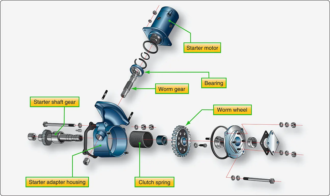 |
| Figure 9. Starter adapter |
Other engines use a starter that drives a ring gear mounted to the propeller hub. [Figure 10] It uses an electric motor and a drive gear that engages as the motor is energized and spins the gear, which moves out and engages the ring gear on the propeller hub cranking the engine for start. [Figure 11] As the engine starts, the starter drive gear is spun back by the engine turning, which disengages the drive gear. [Figure 12] The starter motors on small aircraft also have operational limits with cool down times that should be observed.
 |
| Figure 10. Starter ring gear mounted on the propeller hub |
 |
| Figure 11. Starter drive gear mounting holes and electrical connector |
 |
| Figure 12. Engine starter mounted on the engine |
Reciprocating Engine Starting System Maintenance Practices
A glazed or dirty starter commutator can be cleaned by holding a strip of double-0 sandpaper or a brush seating stone against the commutator as it is turned. The sandpaper or stone should be moved back and forth across the commutator to avoid wearing a groove. Emery paper or carborundum should never be used for this purpose because of their possible shorting action.
Roughness, out-of-roundness, or high-mica conditions are reasons for turning down the commutator. In the case of a high-mica condition, the mica should be undercut after the turning operation is accomplished.
The drive gear should be checked for wear along with the ring gear. The electrical connections should be checked for looseness and corrosion. Also, check the security of the mounting of the housing of the starter.
Troubleshooting Small Aircraft Starting Systems
The troubleshooting procedures listed in Figure 13 are typical of those used to isolate malfunctions in small aircraft starting systems.| Small Aircraft Troubleshooting Procedures | |||
|---|---|---|---|
| Probable Cause | Isolation Procedure | Remedy | |
| Starter will not operate | Defective master switch or circuit | Check master circuit | Repair circuit |
| Defective starter switch or switch circuit | Check switch circuit continuity | Replace switch or wires | |
| Starter lever does not activate switch | Check starter lever adjustment | Adjust starter lever in accordance with manufacturer’s instructions | |
| Defective starter | Check through items above. If another cause is not apparent, starter is defective | Remove and repair or replace starter | |
| Starter motor runs, but does not turn crankshaft | Starter lever adjusted to activate switch without engaging pinion with crankshaft gear | Check starter lever adjustment | Adjust starter lever in accordance with manufacturer’s instructions |
| Defective overrunning clutch or drive | Remove starter and check starter drive and overrunning clutch | Replace defective parts | |
| Damaged starter pinion gear or crankshaft gear | Remove and check pinion gear and crankshaft gear | Replace defective parts | |
| Starter drags | Low battery | Check battery | Charge or replace battery |
| Starter switch or relay contacts burned or dirty | Check contacts | Replace with serviceable unit | |
| Defective starter | Check starter brushes, brush spring tension for solder thrown on brush cover | Repair or replace starter | |
| Starter excessively noisy | Dirty, worn commutator | Clean and check visually | Turn down commutator |
| Worn starter pinion | Remove and examine pinion | Replace starter drive | |
| Worn or broken teeth on crankshaft gears | Remove starter and turn over engine by hand to examine crankshaft gear | Replace crankshaft gear | |
Figure 13. Small aircraft troubleshooting procedures
RELATED POSTS