Proper propeller balancing is essential for minimizing vibration, improving engine smoothness, and extending the service life of both the propeller and aircraft components. Static and dynamic imbalances can reduce performance, increase mechanical stress, and accelerate wear if left uncorrected. This section explains the principles of propeller balancing and outlines the procedures for performing static and dynamic balance checks and applying corrective measures.
Propeller imbalance, which is a source of vibration in an aircraft, may be static or dynamic. Propeller static imbalance occurs when the center of gravity (CG) of the propeller does not coincide with the axis of rotation. Dynamic imbalance occurs when the centers of gravity of similar propeller elements, such as blades or flyweights, do not lie in the same plane of rotation.
Because the propeller assembly is relatively short along the engine crankshaft compared with its diameter, and the blades are secured to the hub so they lie in the same plane perpendicular to the running axis, the dynamic imbalance resulting from improper mass distribution is negligible, provided the blade tracking tolerances are met.
Another type of propeller imbalance, aerodynamic imbalance, results when the thrust (or pull) of the blades is unequal. This type of imbalance can be largely eliminated by checking blade contour and blade angle setting.
Propeller Static Balancing
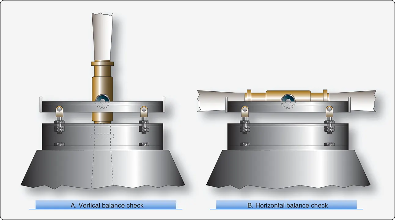
The knife-edge test stand has two hardened steel edges mounted to allow free rotation of an assembled propeller between them. [Figure 1]
 |
| Figure 1. Positions of two-bladed propeller during a balance check |
The knife-edge test stand must be located in a room or area that is free from any air motion, and preferably away from sources of heavy vibration.
The standard method of checking propeller assembly balance involves the following sequence of operations:
- Insert a bushing in the engine shaft hole of the propeller.
- Insert a mandrel or arbor through the bushing.
- Place the propeller assembly so the ends of the arbor rest on the knife edges of the balance stand. The propeller must be free to rotate.
If the propeller is properly balanced statically, it remains in any position in which it is placed. Check a two-bladed propeller assembly for balance: first with the blades in a vertical position and then with the blades in a horizontal position. Repeat the vertical position check with the blade positions reversed; that is, with the blade that was checked in the downward position placed in the upward position.
Check a three-bladed propeller assembly with each blade placed in a downward vertical position. [Figure 2]
 |
| Figure 2. Positions of three-bladed propeller during balance check |
During a propeller static balance check, all blades must be at the same blade angle. Before conducting the balance check, inspect to see that each blade has been set at the same blade angle.
Unless otherwise specified by the manufacturer, an acceptable balance check requires that the propeller assembly have no tendency to rotate in any of the positions previously described. If the propeller balances perfectly in all described positions, it should also balance perfectly in all intermediate positions. When necessary, check for balance in intermediate positions to verify the check in the originally described positions. [Figure 3]
 |
| Figure 3. Static propeller balancing |
When a propeller assembly is checked for static balance and there is a definite tendency for the assembly to rotate, certain corrections to remove the imbalance are allowed.
- The addition of permanent fixed weights at acceptable locations when the total weight of the propeller assembly or parts is under the allowable limit.
- The removal of weight at acceptable locations when the total weight of the propeller assembly or parts is equal to the allowable limit.
The locations for adding or removing weight for propeller imbalance correction have been determined by the propeller manufacturer. The method and point of application of imbalance corrections must be checked to see that they are according to applicable drawings.
Propeller Dynamic Balancing
Propellers can also be dynamically balanced (spin-balanced) with an analyzer kit to reduce the vibration levels of the propeller and spinner assembly. Some aircraft have the system permanently installed, while others require temporary installation of the sensors and cables before balancing. Balancing the propulsion assembly can provide substantial reductions in transmitted vibration and noise to the cabin and also reduces wear and damage to other aircraft and engine components.
Dynamic imbalance may result from mass imbalance or aerodynamic imbalance. Dynamic balancing only reduces vibration caused by mass imbalance of the externally rotating components of the propulsion system. Dynamic balancing does not reduce vibration if the engine or aircraft is in poor mechanical condition.
Defective, worn, or loose parts will make balancing impossible. Several manufacturers make dynamic propeller balancing equipment, and their operating procedures may differ. The typical dynamic balancing system consists of a vibration sensor that is attached to the engine close to the propeller, and an analyzer that calculates the amount and location of balancing weights.
Propeller Balancing Procedure
Position the aircraft directly into the wind (maximum 20 knots) and place chocks at the wheels. After installing the balancing equipment, operate the engine at the specified low-cruise rpm; the dynamic analyzer calculates the balancing weight required at each blade position. After installing the balancing weights, repeat the engine run to verify that vibration levels have been reduced. This process may have to be repeated several times before satisfactory results are achieved.
The following example outlines a typical dynamic balancing procedure, but always refer to the aircraft and propeller manuals when performing any balancing procedure. Dynamic balance is accomplished by using an accurate means of measuring the amount and location of the dynamic imbalance. The number of balance weights installed must not exceed the limits specified by the propeller manufacturer. Follow the dynamic balance equipment manufacturer’s instructions for dynamic balance in addition to the specifications of the propeller.
Most equipment uses an optical pickup that senses reflective tape for rpm reading. Also, an accelerometer is mounted on the engine that senses vibration in inches per second (ips).
Visually inspect the propeller assembly before dynamic balancing. The first runup of a new or overhauled propeller assembly may leave a small amount of grease on the blades and inner surface of the spinner dome. Use Stoddard solvent (or equivalent) to completely remove any grease on the blades or inner surface of the spinner dome. Inspect each propeller blade assembly for evidence of grease leakage. Inspect the inner surface of the spinner dome for evidence of grease leakage. If there is no evidence of grease leakage, lubricate the propeller in accordance with the maintenance manual. If grease leakage is evident, determine the location of the leak and correct before relubricating the propeller and dynamic balancing.
Before dynamic balance, record the number and location of all balance weights. Static balancing is normally performed at a propeller overhaul facility during overhaul or major repair. Twelve equally spaced locations are recommended for weight attachment. Install the balancing weights using aircraft-quality 10-32 or AN-3 type screws or bolts. Balance weight screws attached to the spinner bulkhead must protrude through the self-locking nuts or nut plates a minimum of one thread and a maximum of four threads.
Unless otherwise specified by the engine or airframe manufacturer, Hartzell recommends dynamically balancing the propeller to 0.2 ips or less.
If reflective tape is used for dynamic balancing, remove the tape immediately after balancing is completed. Record the number and location of all dynamic balance weights—and any reconfigured static balance weights—in the propeller logbook.