In modern reciprocating aircraft engines, the piston is a critical component that converts combustion pressure into mechanical motion. Operating under extreme temperatures and pressures, it must be lightweight yet strong enough to withstand continuous thermal and mechanical stress. Advances in aluminum alloy design, cam-ground shaping, and improved ring configurations enhance durability, efficiency, and engine performance. Proper piston construction and fit are essential for maintaining compression, controlling oil consumption, and ensuring reliable powerplant operation.
The piston of a reciprocating engine is a cylindrical member which moves back and forth within a steel cylinder barrel. [Figure 1] The piston acts as a moving wall within the combustion chamber. As the piston moves down in the cylinder, it draws in the fuel/air mixture. As it moves upward, it compresses the charge, ignition occurs, and the expanding gases force the piston downward. This force is transmitted to the crankshaft through the connecting rod. On the return upward stroke, the piston forces the exhaust gases from the cylinder and the cycle repeats.
 |
| Figure 1. A piston |
Piston Construction
The majority of aircraft engine pistons are machined from aluminum alloy forgings. Grooves are machined in the outside surface of the piston to receive the piston rings, and cooling fins are provided on the inside of the piston for greater heat transfer to the engine oil. Pistons may be either the trunk type or the slipper type. [Figure 2] Slipper-type pistons are less common in traditional high-powered air-cooled aircraft engines due to structural and durability considerations. The top of the piston, or head, may be flat, convex, or concave. Recesses may be machined in the piston head to prevent interference with the valves.
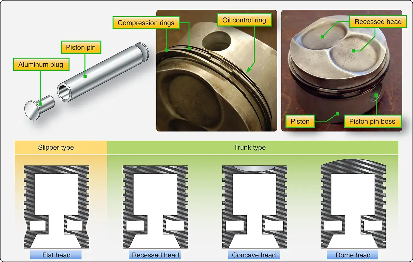 |
| Figure 2. Piston assembly and types of pistons |
Modern engines use cam ground pistons that are a larger diameter perpendicular to the piston pin. This larger diameter keeps the piston straight in the cylinder as the engine warms up from initial start up. As the piston heats up during warm up, the part of the piston in line with the pin has more mass and expands more making the piston completely round. At low temperatures, the piston is oval shaped and, when it warms to operating temperature, it becomes round. This process reduces the tendency of the piston to cock or slap in the cylinder during warm up. When the engine reaches its normal operating temperature, the piston assumes the correct dimensions in the cylinder.
As many as six grooves may be machined around the piston to accommodate the compression rings and oil rings. [Figure 3] The compression rings are installed in the three uppermost grooves; the oil control rings are installed immediately above the piston pin. The piston is usually drilled at the oil control ring grooves to allow surplus oil scraped from the cylinder walls by the oil control rings to pass back into the crankcase. An oil scraper ring is installed at the base of the piston wall or skirt to prevent excessive oil consumption. The portions of the piston walls that lie between ring grooves are called the ring lands. In addition to acting as a guide for the piston head, the piston skirt incorporates the piston-pin bosses. The piston-pin bosses are of heavy construction to enable the heavy load on the piston head to be transferred to the piston pin.
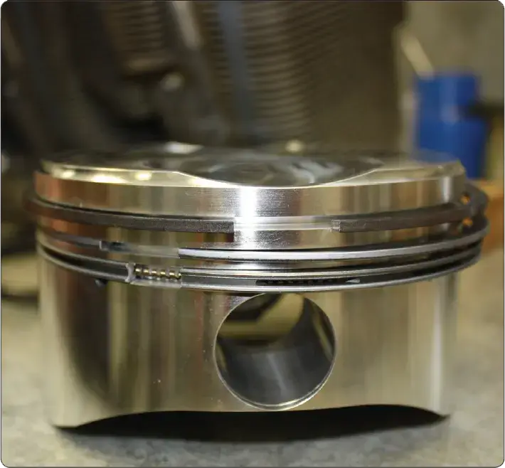 |
| Figure 3. Machined rings around a piston |
| Component Part | Function |
|---|---|
| Piston Head | The top surface that receives the force of combustion. |
| Ring Lands | The high points between the ring grooves that support the rings. |
| Piston Skirt | The side walls that guide the piston and house the pin bosses. |
| Pin Bosses | Heavily reinforced areas that support the piston pin. |
| Aluminum Plugs | Soft metal caps that prevent the steel pin from scoring the cylinder wall. |
Piston Pin
The piston pin joins the piston to the connecting rod. It is machined in the form of a tube from a nickel steel alloy forging, casehardened and ground. The piston pin is sometimes called a wristpin because of the similarity between the relative motions of the piston and the articulated rod and that of the human arm. The piston pin used in modern aircraft engines is the full-floating type, so called because the pin is free to rotate in both the piston and in the connecting rod piston-pin bearing. The piston pin must be held in place to prevent the pin ends from scoring the cylinder walls. A plug of relatively soft aluminum in the pin end provides a good bearing surface against the cylinder wall.