Fuel-injection systems provide more precise fuel metering and distribution than conventional carburetors. Two common aircraft fuel-injection systems are the Bendix/Precision RSA system and the Continental/TCM system, both of which continuously meter fuel in proportion to engine airflow.
The fuel-injection system has many advantages over a conventional carburetor system. There is less danger of induction system icing, since the drop in temperature due to fuel vaporization takes place in or near the cylinder. Acceleration is also improved because of the positive action of the injection system. In addition, fuel injection improves fuel distribution. This reduces the overheating of individual cylinders often caused by variation in mixture due to uneven distribution. The fuel-injection system also gives better fuel economy than a system in which the mixture to most cylinders must be richer than necessary so that the cylinder with the leanest mixture operates properly.
Fuel-injection systems vary in their details of construction, arrangement, and operation. The Bendix and Continental fuel-injection systems are discussed in this section. They are described to provide an understanding of the operating principles involved. For the specific details of any one system, consult the manufacturer’s instructions for the equipment involved.
Bendix/Precision Fuel-Injection System
The Bendix inline stem-type regulator injection system (RSA) series consists of an injector, flow divider, and fuel discharge nozzle. It is a continuous-flow system which measures engine air consumption and uses airflow forces to control fuel flow to the engine. The fuel distribution system to the individual cylinders is obtained by the use of a fuel flow divider and air bleed nozzles.
Fuel Injector
The fuel injector assembly consists of:
- An airflow section,
- A regulator section, and
- A fuel metering section. Some fuel injectors are equipped with an automatic mixture control unit.
Airflow Section
The airflow consumption of the engine is measured by sensing impact pressure and venturi throat pressure in the throttle body. These pressures are vented to the two sides of an air diaphragm. A cutaway view of the airflow measuring section is shown in Figure 1.
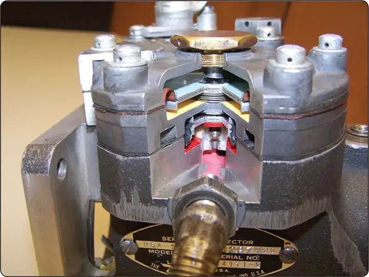 |
| Figure 1. Cutaway view of airflow measuring section |
Movement of the throttle valve causes a change in engine air consumption. This results in a change in the air velocity in the venturi. When airflow through the engine increases, the pressure on the left of the diaphragm is lowered due to the drop in pressure at the venturi throat. [Figure 2]
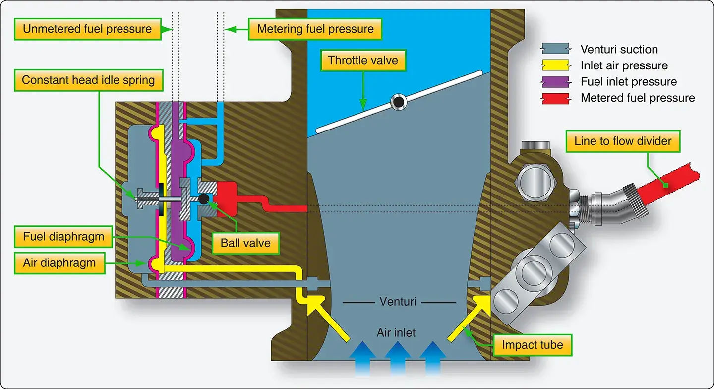 |
| Figure 2. Airflow section of a fuel injector |
As a result, the diaphragm moves to the left, opening the ball valve. Contributing to this force is the impact pressure that is picked up by the impact tubes. [Figure 3]
 |
| Figure 3. Impact tubes for inlet air pressure |
This pressure differential is referred to as the “air metering force.” This force is accomplished by channeling the impact and venturi suction pressures to opposite sides of a diaphragm. The difference between these two pressures becomes a usable force that is equal to the area of the diaphragm times the pressure difference.
Regulator Section
The regulator section consists of a fuel diaphragm that opposes the air metering force. Fuel inlet pressure is applied to one side of the fuel diaphragm and metered fuel pressure is applied to the other side. The differential pressure across the fuel diaphragm is called the fuel metering force. The fuel pressure shown on the ball side of the fuel diaphragm is the pressure after the fuel has passed through the fuel strainer and the manual mixture control rotary plate and is referred to as metered fuel pressure. Fuel inlet pressure is applied to the opposite side of the fuel diaphragm. The ball valve attached to the fuel diaphragm controls the orifice opening and fuel flow through the forces placed on it. [Figure 4]
 |
| Figure 4. Fuel diaphragm with ball valve attached |
The distance the ball valve opens is determined by the difference between the pressures acting on the diaphragms. This difference in pressure is proportional to the airflow through the injector. Thus, the volume of airflow determines the rate of fuel flow.
Under low power settings, the difference in pressure created by the venturi is insufficient to accomplish consistent regulation of the fuel. A constant-head idle spring is incorporated to provide a constant fuel differential pressure. This allows an adequate final flow in the idle range.
Fuel Metering Section
The fuel metering section is attached to the air metering section and contains an inlet fuel strainer, a manual mixture control valve, an idle valve, and the main metering jet. [Figure 5]
 |
| Figure 5. Fuel metering section of the injector |
The idle valve is connected to the throttle valve by means of an external adjustable link. In some injector models, a power enrichment jet is also located in this section.
The purpose of the fuel metering section is to meter and control the fuel flow to the flow divider. [Figure 6]
 |
| Figure 6. Fuel inlet and metering |
The manual mixture control valve produces full rich condition when the lever is against the rich stop, and a progressively leaner mixture as the lever is moved toward idle cutoff. Both idle speed and idle mixture may be adjusted externally to meet individual engine requirements.
Flow Divider
The metered fuel is delivered from the fuel control unit to a pressurized flow divider. This unit keeps metered fuel under pressure, divides fuel to the various cylinders at all engine speeds, and shuts off the individual nozzle lines when the control is placed in idle cutoff.
Referring to the diagram in Figure 7, metered fuel pressure enters the flow divider through a channel that permits fuel to pass through the inside diameter of the flow divider needle.
 |
| Figure 7. Flow divider |
At idle speed, the fuel pressure from the regulator must build up to overcome the spring force applied to the diaphragm and valve assembly. This moves the valve upward until fuel can pass out through the annulus of the valve to the fuel nozzle. [Figure 8]
 |
| Figure 8. Flow divider cutaway |
Since the regulator meters and delivers a fixed amount of fuel to the flow divider, the valve opens only as far as necessary to pass this amount to the nozzles. At idle, the opening required is very small; the fuel for the individual cylinders is divided at idle by the flow divider.
As fuel flow through the regulator is increased above idle requirements, fuel pressure builds up in the nozzle lines. This pressure fully opens the flow divider valve, and fuel distribution to the engine becomes a function of the discharge nozzles.
A fuel pressure gauge, calibrated in pounds per hour fuel flow, can be used as a fuel flow meter with the Bendix RSA injection system. This gauge is connected to the flow divider and senses the pressure being applied to the discharge nozzle. This pressure is in direct proportion to the fuel flow and indicates the engine power output and fuel consumption.
Fuel Discharge Nozzles
The fuel discharge nozzles are of the air bleed configuration. There is one nozzle for each cylinder located in the cylinder head. [Figure 9]
 |
| Figure 9. Fuel nozzle assembly |
The nozzle outlet is directed into the intake port. Each nozzle incorporates a calibrated jet. The jet size is determined by the available fuel inlet pressure and the maximum fuel flow required by the engine. The fuel is discharged through this jet into an ambient air pressure chamber within the nozzle assembly. Before entering the individual intake valve chambers, the fuel is mixed with air to aid in atomizing the fuel. Fuel pressure, before the individual nozzles, is in direct proportion to fuel flow; therefore, a simple pressure gauge can be calibrated in fuel flow in gallons per hour and be employed as a flow meter. Engines modified with turbosuperchargers must use shrouded nozzles. By the use of an air manifold, these nozzles are vented to the injector air inlet pressure.
Continental/TCM Fuel-Injection System
The Continental fuel-injection system injects fuel into the intake valve port in each cylinder head. [Figure 10]
 |
| Figure 10. Continental/TCM Fuel-Injection System |
The system consists of a fuel injector pump, a control unit, a fuel manifold, and a fuel discharge nozzle. It is a continuous-flow type, which controls fuel flow to match engine airflow. The continuous-flow system permits the use of a rotary-vane pump that does not require timing to the engine.
Fuel-Injection Pump
The fuel pump is a positive-displacement, rotary-vane type with a splined shaft for connection to the accessory drive system of the engine. [Figure 11]
 |
| Figure 11. Fuel pump |
A spring-loaded, diaphragm-type relief valve is provided. The relief valve diaphragm chamber is vented to atmospheric pressure. A sectional view of a fuel-injection pump is shown in Figure 12.
 |
| Figure 12. Fuel injection pump |
Fuel enters at the swirl well of the vapor separator. Here, vapor is separated by a swirling motion so that only liquid fuel is delivered to the pump. The vapor is drawn from the top center of the swirl well by a small pressure jet of fuel and is directed into the vapor return line. This line carries the vapor back to the fuel tank.
Ignoring the effect of altitude or ambient air conditions, the use of a positive-displacement, engine-driven pump means that changes in engine speed affect total pump flow proportionally. Since the pump provides greater capacity than is required by the engine, a recirculation path is required. By arranging a calibrated orifice and relief valve in this path, the pump delivery pressure is also maintained in proportion to engine speed. These provisions assure proper pump pressure and fuel delivery for all engine operating speeds.
A check valve is provided so that boost pump pressure to the system can bypass the engine-driven pump for starting. This feature also suppresses vapor formation under high ambient temperatures of the fuel and permits use of the auxiliary pump as a source of fuel pressure in the event of engine-driven pump failure.
Air-Fuel Control Unit
The function of the air-fuel control assembly is to control engine air intake and to set the metered fuel pressure for proper air-fuel ratio. The air throttle is mounted at the manifold inlet and its butterfly valve, positioned by the throttle control in the aircraft, controls the flow of air to the engine. [Figure 13]
 |
| Figure 13. Fuel air control unit |
The air throttle assembly is an aluminum casting which contains the shaft and butterfly-valve assembly. The casting bore size is tailored to the engine size, and no venturi or other restriction is used.
Fuel Control Assembly
The fuel control body is made of bronze for best bearing action with the stainless steel valves. Its central bore contains a metering valve at one end and a mixture control valve at the other end. Each stainless steel rotary valve includes a groove which forms a fuel chamber.
Fuel enters the control unit through a strainer and passes to the metering valve. [Figure 14]
 |
| Figure 14. Dual fuel control assembly |
This rotary valve has a cam-shaped edge on the outer part of the end face. The position of the cam at the fuel delivery port controls the fuel passed to the manifold valve and the nozzles. The fuel return port connects to the return passage of the center metering plug. The alignment of the mixture control valve with this passage determines the amount of fuel returned to the fuel pump.
By connecting the metering valve to the air throttle, fuel flow is properly proportioned to airflow to maintain the correct air-fuel ratio. A control lever is mounted on the mixture control valve shaft and connected to the flight deck mixture control.
Fuel Manifold Valve
The fuel manifold valve contains a fuel inlet, a diaphragm chamber, and outlet ports for the lines to the individual nozzles. [Figure 15]
 |
| Figure 15. Fuel manifold valve assembly |
The spring-loaded diaphragm operates a valve in the central bore of the body. Fuel pressure provides the force for moving the diaphragm. The diaphragm is enclosed by a cover that retains the diaphragm loading spring. When the valve is down against the lapped seat in the body, the fuel lines to the cylinders are closed off. The valve is drilled for passage of fuel from the diaphragm chamber to its base, and a ball valve is installed within the valve. All incoming fuel must pass through a fine screen installed in the diaphragm chamber.
From the fuel-injection control valve, fuel is delivered to the fuel manifold valve, which provides a central point for dividing fuel flow to the individual cylinders. In the fuel manifold valve, a diaphragm raises or lowers a plunger valve to open or close the individual cylinder fuel supply ports simultaneously.
Fuel Discharge Nozzle
The fuel discharge nozzle is located in the cylinder head with its outlet directed into the intake port. The nozzle body contains a drilled central passage with a counterbore at each end. [Figure 16]
 |
| Figure 16. Fuel discharge nozzles |
The lower end is used as a chamber for air-fuel mixing before the spray leaves the nozzle. The upper bore contains a removable orifice for calibrating the nozzles. Nozzles are calibrated in several ranges, and all nozzles furnished for one engine are of the same range and are identified by a letter stamped on the hex of the nozzle body.
Drilled radial holes connect the upper counterbore with the outside of the nozzle body. These holes enter the counterbore above the orifice and draw air through a cylindrical screen fitted over the nozzle body. A shield is press-fitted on the nozzle body and extends over the greater part of the filter screen, leaving an opening near the bottom. This provides both mechanical protection and an abrupt change in the direction of airflow which keeps dirt and foreign material out of the nozzle interior.
Quick Review: Aircraft Fuel Injection
What are the primary operational advantages of an engine fuel-injection system over a conventional float carburetor?
- Elimination of Induction Icing: Because fuel vaporization occurs directly in or near the hot cylinder ports rather than inside a venturi throat, the risk of fuel evaporation refrigeration icing is virtually eliminated.
- Improved Cylinder Cooling & Economy: Uniform fuel delivery prevents individual cylinders from running excessively lean and overheating, allowing the entire engine to run on a leaner, more efficient overall cruise mixture.
- Instant Acceleration: The positive, pressurized action of continuous-flow metering elements ensures rapid and smooth throttle responses without acceleration lag.
How do the air and fuel diaphragms inside a Bendix RSA injector combine to meter fuel?
- Air Metering Force: Impact tubes and a main venturi vent differential air pressures to opposite sides of an air diaphragm. Increased engine airflow drives this diaphragm to shift, physically opening the ball valve.
- Fuel Metering Force: Unmetered inlet fuel pressure and metered fuel pressure act on opposite sides of a fuel diaphragm, providing an opposing force.