Aircraft exhaust systems perform more than simply directing exhaust gases away from the engine. On turbocharged reciprocating engines, the exhaust system also drives the turbocharger, while turbine engines rely on carefully designed exhaust nozzles to optimize exhaust gas velocity and engine thrust. Understanding exhaust system maintenance, repair procedures, and nozzle design is essential for ensuring safe operation, efficient engine performance, and long service life.
When a turbocharger or turbosupercharger system is installed, the engine exhaust system operates under greatly increased pressure and temperature conditions. Extra precautions should be taken in exhaust system care and maintenance. During high-altitude operation, the exhaust system pressure is maintained at or near sea level values. Due to the pressure differential, any leaks in the system allow the exhaust gases to escape with torch-like intensity that can severely damage adjacent structures.
A common cause of malfunction is coke deposits (carbon buildup) in the waste gate unit causing erratic system operation. Excessive deposit buildups may cause the waste gate valve to stick in the “closed” position, causing an overboost condition. Coke deposit buildup in the turbocharger itself causes a gradual loss of power in flight and low manifold pressure reading prior to takeoff.
Experience has shown that periodic de-coking, or removal of carbon deposits, is necessary to maintain peak efficiency. Clean, repair, overhaul, and adjust the system components and controls in accordance with the applicable manufacturer’s instructions.
Augmentor Exhaust System
On exhaust systems equipped with augmentor tubes, the augmentor tubes should be inspected at regular intervals for proper alignment, security of attachment, and general overall condition. Even where augmentor tubes do not contain heat exchanger surfaces, they should be inspected for cracks along with the remainder of the exhaust system.
Cracks in augmentor tubes can present a fire or carbon monoxide hazard by allowing exhaust gases to enter the nacelle, wing, or cabin areas.
Exhaust System Repairs
It is generally recommended that exhaust stacks, mufflers, tailpipes, etc., be replaced with new or reconditioned components rather than repaired. Welded repairs to exhaust systems are complicated by the difficulty of accurately identifying the base metal so that the proper repair materials can be selected. Changes in composition and grain structure of the original base metal further complicate the repair.
However, when welded repairs are necessary, the original contours should be retained; the exhaust system alignment must not be warped or otherwise affected. Repairs or sloppy weld beads that protrude internally are not acceptable as they cause local hot spots and may restrict exhaust gas flow.
The proper hardware and clamps should always be used when repairing or replacing exhaust system components. Steel or low-temperature self-locking nuts should not be substituted for brass or special high-temperature locknuts used by the manufacturer. Old gaskets should never be reused. When disassembly is necessary, gaskets should be replaced with new ones of the same type provided by the manufacturer.
Turbine Engine Exhaust Nozzles
Turbine engines have several different types of exhaust nozzles depending upon the type of engine. Turboshaft engines in helicopters can have an exhaust nozzle that forms a divergent duct. This type of nozzle would not provide any thrust, all engine power going to rotate the rotors, improving helicopter hovering abilities.
Turbofan engines generally fall into either ducted-fan or unducted-fan configurations. Ducted fan engines take the fan airflow and direct it through closed ducts along the engine. Then, it flows into a common exhaust nozzle. The core exhaust flow and the fan flow mix and flow from the engine through this mixed nozzle.
The unducted fan has two nozzles, one for the fan airflow and one for the core airflow. These exhaust streams are discharged separately into the ambient air through separate nozzles. [Figure 1]
 |
| Figure 1. Path of both core exhaust flow and fan flow from the engine to separate nozzles |
The unducted engine or the separate nozzle engine handles high amounts of airflow. The fan air which creates most of the thrust (80–85 percent total thrust) must be directed through the fan blades and exit vanes with as little turbulence as possible. [Figure 2]
 |
| Figure 2. Fan air is directed through the fan blades and exit vanes |
The core airflow needs to be straightened as it comes from the turbine. Through the use of a converging nozzle, the exhaust gases increase in velocity before they are discharged from the exhaust nozzle. Increasing the velocity of the gases increases their momentum and increases the thrust produced (20–15 percent total thrust). Most of the energy of the gases has been absorbed to drive the fan through the low-pressure turbine stages.
Turboprop Tailpipe Layout
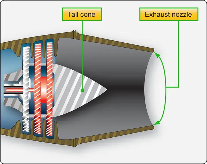
Turboprop exhaust nozzles provide small amounts of thrust (10–15 percent) but are mainly used to discharge the exhaust gases from the aircraft. Most of the energy has been transferred to the propeller. On some turboprop aircraft, an exhaust duct is often referred to as a tailpipe, although the duct itself is essentially a simple stainless-steel conical or cylindrical pipe. The assembly also includes an engine tail cone and the struts inside the duct. The tail cone and the struts add strength to the duct, impart an axial direction to the gas flow, and smooth the gas flow.
In a typical installation, the tailpipe assembly is mounted in the nacelle and attached at its forward end to the firewall. The forward section of the tailpipe is funnel-shaped and surrounds but does not contact the turbine exhaust section. This arrangement forms an annular gap that serves as an air ejector for the air surrounding the engine hot section. As the high-velocity exhaust gases enter the tailpipe, a low-pressure effect is produced which causes the air around the engine hot section to flow through the annular gap into the tailpipe.
The rear section of the tailpipe is secured to the airframe by two support arms, one on each side of the tailpipe. The support arms are attached to the upper surface of the wing in such a way that allows movement fore and aft to compensate for expansion. The tailpipe assembly is wrapped in an insulating blanket to shield the surrounding area from the high heat produced by the exhaust gases. Such blankets may be made of a stainless-steel laminated sheet on the outside and fiberglass on the inside. This is used when the engine exhaust is located some distance from the edge of the wing or aircraft structure.
Immediately aft of the turbine outlet, and usually just forward of the flange to which the exhaust duct is attached, the engine is instrumented for turbine discharge pressure. One or more pressure probes are inserted into the exhaust duct to provide adequate sampling of the exhaust gases. In large engines, it is not practical to measure the internal temperature at the turbine inlet, so the engine is often also instrumented for exhaust gas temperature at the turbine outlet.
Convergent Exhaust Nozzle
As the exhaust gases exit the rear of the engine, they flow into the exhaust nozzle. [Figure 3]
 |
| Figure 3. Exhaust gases exit the rear of the engine through the exhaust nozzle |
The first part of the exhaust nozzle and the exhaust plug form a divergent duct to reduce turbulence in the airflow, then the exhaust gases flow into the convergent component of the exhaust nozzle where the flow is restricted by a smaller outlet opening. Since this forms a convergent duct, the gas velocity is increased, providing increased thrust.
The restriction of the opening of the outlet of the exhaust nozzle is limited by two factors. If the nozzle opening is too big, thrust is being wasted. If it is too small, the flow is choked in the other components of the engine. In other words, the exhaust nozzle acts as an orifice, the size of which determines the density and velocity of the gases as they emerge from the engine. This is critical to thrust performance. Adjusting the area of the exhaust nozzle changes both the engine performance and the exhaust gas temperature.
When the velocity of the exhaust gases at the nozzle opening becomes Mach 1, the flow passes only at this speed—it does not increase or decrease. When sufficient flow exists to maintain Mach 1 at the nozzle opening, any additional flow restricted by the opening creates what is known as a choked nozzle. The extra flow builds up pressure in the nozzle, which is sometimes called pressure thrust.
A differential in pressure exists between the inside of the nozzle and the ambient air. By multiplying this pressure difference by the area of the nozzle opening, pressure thrust can be calculated. Many engines cannot develop pressure thrust because most of the energy is used to drive turbines that turn propellers, large fans, or helicopter rotors.
Convergent-Divergent Exhaust Nozzle
Whenever the engine pressure ratio is high enough to produce exhaust gas velocities which might exceed Mach 1 at the engine exhaust nozzle, more thrust can be gained by using a convergent-divergent type of nozzle. [Figure 4]
 |
| Figure 4. A convergent-divergent nozzle can be used to help produce more thrust when exhaust gas velocities are greater than Mach 1 |
The advantage of a convergent-divergent nozzle is greatest at high Mach numbers because of the resulting higher pressure ratio across the engine exhaust nozzle.
To ensure that a constant weight or volume of a gas flows past any given point after sonic velocity is reached, the rear part of a supersonic exhaust duct is enlarged to accommodate the additional weight or volume of a gas that flows at supersonic rates. If this is not done, the nozzle does not operate efficiently. This is the divergent section of the exhaust duct.
When a divergent duct is used in combination with a conventional exhaust duct, it is called a convergent-divergent exhaust duct. In the convergent-divergent, or C-D nozzle, the convergent section is designed to handle the gases while they remain subsonic, and to deliver the gases to the throat of the nozzle just as they attain sonic velocity.
The divergent section handles the gases, further increasing their velocity, after they emerge from the throat and become supersonic. As the gas flows from the throat of the nozzle, it becomes supersonic (Mach 1 and above) and then passes into the divergent section of the nozzle. Since it is supersonic, it continues to increase in velocity. This type of nozzle is generally used on very high-speed aerospace vehicles.
Quick Review: Exhaust Systems and Nozzle Design
Why are exhaust leaks in a turbocharged engine considered far more hazardous than in a naturally aspirated engine?
How do carbon coke deposits inside a turbocharger system affect overall engine performance?
- Sticking Waste Gate: Excessive coke accumulation can cause the waste gate valve to stick completely in the closed position, leading to an uncontrolled and highly damaging engine overboost condition.
- Rotor Contamination: Coke deposits inside the turbocharger core restrict turbine efficiency, manifesting as low pre-takeoff manifold pressure readings and a gradual, progressive loss of power in flight.