The auxiliary lift devices group includes wing flaps, spoilers, speed brakes, slats, leading edge flaps, and slots. These devices modify the aerodynamic characteristics of the wing to improve aircraft performance during specific phases of flight, particularly takeoff, climb, approach, and landing. Auxiliary lift devices can be divided into two primary subgroups: lift-augmenting devices and lift-decreasing devices. Lift-augmenting devices increase lift at lower airspeeds, while lift-decreasing devices reduce lift and increase drag to assist in descent, speed control, and landing.
Lift-augmenting devices include trailing-edge flaps, leading-edge flaps (slats), and slots. Lift-decreasing devices consist primarily of spoilers and speed brakes.
Lift-Augmenting Devices
Flaps are mounted on the trailing edge of the wing and are movable to increase the camber and, in some cases, the effective wing area. This results in increased lift at lower airspeeds, allowing for shorter takeoff distances and lower landing speeds. Many flap designs are retractable and fair smoothly into the wing contour when not in use, while simpler designs consist of a portion of the wing skin extending into the airstream to increase drag and lift simultaneously.
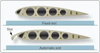
Leading-edge flaps, commonly referred to as slats, are airfoil-shaped surfaces that extend from and retract into the leading edge of the wing. Some installations create a slot, which is an opening between the extended slat and the wing leading edge. [Figure 1] At low airspeeds, airflow through the slot re-energizes the boundary layer over the upper surface of the wing, delaying airflow separation, increasing maximum lift, and improving controllability near the stall.
 |
| Figure 1. Types of wing flaps |
Other aircraft designs incorporate fixed slots built permanently into the wing leading edge. During cruise flight, both trailing-edge flaps and leading-edge slats are fully retracted into the wing structure to minimize drag. Slats are movable control surfaces attached to the leading edges of the wings and are particularly effective in improving low-speed handling characteristics.
[ad-mid]
When the slat is in the closed position, it forms a smooth continuation of the wing’s leading edge. When extended forward, a slot is created between the slat and the wing leading edge. This configuration increases lift and improves handling at low airspeeds, allowing safe operation below normal landing speeds. [Figure 2]
 |
| Figure 2. Wing slots |
Lift-Decreasing Devices
Lift-decreasing devices include speed brakes and spoilers, which are used to reduce lift and increase drag. In some aircraft installations, two types of spoilers are used. Ground spoilers extend only after touchdown and significantly reduce wing lift, transferring the aircraft’s weight to the landing gear to improve braking effectiveness.
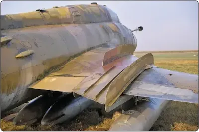
Flight spoilers assist with lateral control by deploying on the wing where the aileron is deflected upward. When operated as speed brakes, spoiler panels on both wings extend simultaneously to increase drag and reduce airspeed. In-flight spoilers may also be installed along the fuselage sides, beneath the fuselage, or near the tail section. [Figure 3]
 |
| Figure 3. Speed brake |
In certain aircraft designs, the spoiler panel on the up-aileron wing rises more than the spoiler on the opposite wing. This configuration allows the spoilers to provide both speed brake function and roll control at the same time.
[ad-long]Winglets
Winglets are near-vertical extensions at the wingtips designed to reduce the strength of wingtip vortices. These vortices create induced drag, particularly at higher lift coefficients. By weakening the vortices, winglets improve aerodynamic efficiency, reduce fuel consumption, and extend aircraft range. Figure 4 illustrates a Learjet 60 equipped with winglets.
 |
| Figure 4. Winglets on a Bombardier Learjet 60 |
Canard Wings
A canard wing configuration places a small wing or horizontal airfoil ahead of the main lifting surfaces, rather than behind them as in conventional aircraft. The canard may be fixed or movable and may incorporate elevators for pitch control. This configuration can improve stall characteristics and pitch stability, as the canard typically stalls before the main wing. Examples of canard-equipped aircraft include the Rutan VariEze and the Beechcraft 2000 Starship. [Figures 5 and 6]
 |
| Figure 5. Canard wings on a Rutan VariEze |
 |
| Figure 6. The Beechcraft 2000 Starship has canard wings |
Wing Fences
Wing fences are flat, vertical metal plates mounted on the upper surface of the wing. Their purpose is to restrict spanwise airflow and prevent premature wingtip stall, especially on swept-wing aircraft. By controlling airflow at high angles of attack, wing fences improve slow-speed handling and provide more predictable stall behavior. [Figure 7]
 |
| Figure 7. Aircraft stall fence |
