The air entrance is designed to conduct incoming air to the compressor with a minimum energy loss resulting from drag or ram pressure loss; that is, the flow of air into the compressor should be free of turbulence to achieve maximum operating efficiency. Proper inlet design contributes materially to aircraft performance by increasing the ratio of compressor discharge pressure to duct inlet pressure.
This is also referred to as the compressor pressure ratio. This ratio is the outlet pressure divided by the inlet pressure. The amount of air passing through the engine is dependent upon three factors:
- The compressor speed (rpm)
- The forward speed of the aircraft
- The density of the ambient (surrounding) air
Turbine inlet type is dictated by the type of gas turbine engine. A high-bypass turbofan engine inlet is completely different from a turboprop or turboshaft inlet. Large gas turbine-powered aircraft almost always have a turbofan engine. The inlet on this type of engine is bolted to the front (A flange) of the engine. These engines are mounted on the wings, or nacelles, on the aft fuselage, and a few are in the vertical fin. A typical turbofan inlet can be seen in Figure 1.
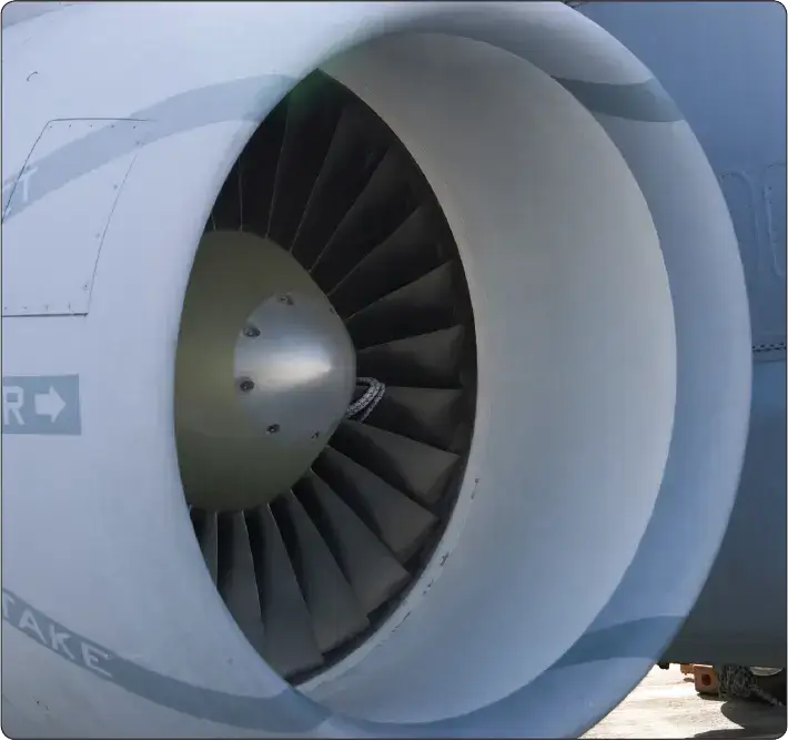 |
| Figure 1. Typical turbofan inlet |
Since on most modern turbofan engines the huge fan is the first part of the aircraft the incoming air comes into contact with, icing protection must be provided. This prevents chucks of ice from forming on the leading edge of the inlet, breaking loose, and damaging the fan. Warm air is bled from the engine’s compressor and is ducted through the inlet to prevent ice from forming. If inlet guide vanes are used to straighten the air flow, then they also have anti-icing air flowing through them. The inlet also contains some sound-reducing materials that absorb the fan noise and make the engine quieter.
Turboprops and turboshafts can use an inlet screen to help filter out ice or debris from entering the engine. A deflector vane and a heated inlet lip are used to prevent ice or large chunks from entering the engine. On military aircraft, the divided entrance permits the use of very short ducts with a resultant small pressure drop through skin friction. Military aircraft can fly at speeds above Mach 1, but the airflow through the engine must always stay below Mach 1. Supersonic air flow in the engine would destroy the engine. By using convergent and divergent shaped ducts, the air flow is controlled and dropped to subsonic speeds before entering the engine. Supersonic inlets are used to slow the incoming engine air to less than Mach 1 before it enters the engine.
Engine-Mounted Inlets
Several large commercial aircraft and large military aircraft use wing-mounted engines. In a few cases, such as the DC-10 and L-1011 , a combination of wing mounted and vertical stabilizer mounted engines are used. In these cases, the air inlet duct is located directly in front of the compressor and is mounted to the engine. Integral mounting of the inlet with an engine reduces air inlet length, which increases efficiency. [Figure 2] In addition to the wing- and vertical stabilizer mounted engines, some commercial aircraft and a majority of small business jets are fitted with aft fuselage mounted engines. The air inlet ducts on engines mounted in this fashion are identical to air inlet ducts on wing-mounted engines; the duct is relatively short and is mounted directly to the engine. [Figure 3]
 |
| Figure 2 . A Lockheed L-1011 Tristar is designed with wing-mounted engines and an engine in the vertical stabilizer. The air inlet ducts on all of these engines are mounted to the engine and positioned directly in front of the compressor |
 |
| Figure 3. Engines mounted on the aft fuselage accommodate short, efficient air inlet ducts that attach to the front of each engine |
Wing-Mounted Inlets
Some aircraft with engines mounted inside the wings feature air inlet ducts in the wing's leading edge. Aircraft such as the Aerospatiale Caravelle, the de Havilland® Comet, and the de Havilland Vampire all use wing-mounted inlets. Typically, wing-mounted inlet ducts are positioned near the wing root area. [Figure 4]
 |
| Figure 4. The Hawker-Siddeley "Nimrod" uses aerodynamically shaped, wing -mounted air inlet ducts to reduce drag |
Fuselage-Mounted Inlets
Engines mounted inside a fuselage typically use air inlet ducts located near the front of the fuselage. For example, many early military aircraft were designed with an air inlet duct in the nose of the fuselage. In addition, some modern supersonic military aircraft have inlet ducts located just under the aircraft nose. Although using an air inlet duct of this type enables the aircraft manufacturer to build a more aerodynamically efficient aircraft, the increased length of the inlet duct introduces some inefficiency. [Figure 5)
 |
| Figure 5 . The single-entrance inlet duct takes full advantage of ram effect much like engine-mounted air inlet ducts. Although the aircraft is aerodynamically clean, the length of the duct makes it less efficient than engine-mounted types |
Some military aircraft use air inlet ducts mounted on the sides of the fuselage. This arrangement works well for both single- and twin-engine aircraft. By mounting an air inlet duct on each side of an aircraft, the duct length can be shortened without adding a significant amount of drag to the aircraft. However, a disadvantage to this arrangement is that some sudden flight maneuvers can cause an imbalance in ram air pressure between the two ducts. An air pressure imbalance acting on a compressor face can result in a slight loss of power. [Figure 6)
 |
| Figure 6. The short length of divided-entrance inlet ducts is relatively efficient |
Subsonic Inlets
A typical subsonic air inlet consists of a fixed geometry duct with a diameter that progressively increases from front to back. This divergent shape works like a venturi; as the intake air spreads out, the velocity of the air decreases and the pressure increases. This added pressure contributes significantly to engine efficiency after the aircraft reaches its design cruising speed. At this speed, the compressor reaches its optimum aerodynamic efficiency and produces the most compression at the best fuel economy. It is at this design cruise speed that the inlet, compressor, combustor, turbine, and exhaust duct are designed to match each other as a unit. If any mismatch occurs because of damage, contamination, or ambient conditions, engine performance suffers.
Supersonic Inlets
On supersonic aircraft, a typical air inlet duct has either a fixed or variable geometry with a diameter that progressively decreases, then increases from front to back. This convergent-divergent shape is used to slow the incoming airflow to subsonic speed before it reaches the compressor. In addition to the convergent-divergent shape, many supersonic inlet ducts employ a movable plug or throat that changes duct geometry according to flight conditions. This variable geometry is necessary so that the duct can accommodate a wide range of flight speeds.
| Inlet Type | Duct Shape | Primary Purpose | Common Application |
|---|---|---|---|
| Subsonic | Divergent | Decrease velocity; Increase static pressure | Commercial Airliners |
| Supersonic | Convergent-Divergent | Slow air to subsonic speeds (Shockwave control) | Fighter Jets / Concorde |
| Bellmouth | Convergent (Rounded) | Maximum efficiency at zero/low airspeed | Test Cells / Helicopters |
Bellmouth Inlets
Bellmouth inlet ducts have a convergent profile that is designed for obtaining high aerodynamic efficiency when stationary or in slow flight. Bellmouth inlet ducts are typically used on helicopters, some slow-moving aircraft, and on engines being run in ground test stands. A typical bellmouth inlet duct is short in length and has rounded shoulders that offer little air resistance. However, because their shape produces a great deal of drag in forward flight, bellmouth inlet ducts are typically not used on highspeed aircraft. Because bellmouth inlet ducts are most efficient when stationary, engine manufacturers typically collect engine performance data from engines fitted with a bellmouth inlet duct.
For additional information on inlet systems, refer to the discussion on Turbine Engine Entrance Ducts post.
📂 Technical Summary: Inlet Systems
- Ram Recovery The primary goal of the inlet is to convert the velocity of incoming air into static pressure (ram pressure) with minimal energy loss.
- Divergent Design (Subsonic) Subsonic inlets use a divergent shape (increasing area) to slow airflow and increase pressure before it hits the compressor face.
- Supersonic Management Supersonic air must be slowed to subsonic speeds using Convergent-Divergent (C-D) ducts to prevent engine damage and maintain efficiency.
- Inlet Anti-Icing Engine bleed air is used to heat the inlet lip, preventing ice from breaking loose and causing Foreign Object Damage (FOD) to the fan or compressor.
- Bellmouth Efficiency Primarily used for ground testing and helicopters, bellmouths offer the highest aerodynamic efficiency when static but high drag at high speeds.