The dimensional inspection is used to assure that the engine’s component parts and clearances meet the manufacturer’s specifications. These specs are listed in a table of limits, which lists serviceable limits and the manufacturer’s new part maximum and minimum dimensions. Many measuring tools are used to perform the dimensional inspection of the engine.
Cylinder Barrel
Inspect the cylinder barrel for wear, using a cylinder bore gauge [Figure 1], a telescopic gauge, and micrometer or an inside micrometer. |
| Figure 1. A cylinder bore gauge |
Dimensional inspection of the barrel consists of the following measurements:
- Maximum taper of cylinder walls
- Maximum out-of-roundness
- Bore diameter
- Step
- Fit between piston skirt and cylinder
All measurements involving cylinder barrel diameters must be taken at a minimum of two positions 90° apart in the particular plane being measured. It may be necessary to take more than two measurements to determine the maximum wear. Taper of the cylinder walls is the difference between the diameter of the cylinder barrel at the bottom and the diameter at the top. The cylinder is usually worn larger at the top than at the bottom. This taper is caused by the natural wear pattern. At the top of the stroke, the piston is subjected to greater heat and pressure and more erosive environment than at the bottom of the stroke. Also, there is greater freedom of movement at the top of the stroke. Under these conditions, the piston wears the cylinder wall more at the top of the cylinder. In most cases, the taper ends with a ridge, that must be removed during overhaul. [Figure 2]
 |
| Figure 2. Ridge or step formed in an engine cylinder |
Where cylinders are built with an intentional choke, measurement of taper becomes more complicated. Cylinder choke is where the top of the cylinder has been made with the very top diameter of the cylinder smaller, to compensate for wear and expansion during operation. It is necessary to know exactly how the size indicates wear or taper. Taper can be measured in any cylinder by a cylinder dial gauge as long as there is not a sharp step. The dial gauge tends to ride up on the step and causes inaccurate readings at the top of the cylinder.
The measurement for out-of-roundness is usually taken at the top of the cylinder. However, a reading should also be taken at the skirt of the cylinder to detect dents or bends caused by careless handling. A step, or ridge, is formed in the cylinder by the wearing action of the piston rings. [Figure 2] The greatest wear is at the top of the ring travel limit. The ridge that results is likely to cause damage to the rings or piston. If the step exceeds tolerances, it should be removed by grinding the cylinder oversize, or it should be blended by hand-stoning to break the sharp edge. A step also may be found where the bottom ring reaches the lowest travel. This step is rarely found to be excessive, but it should be checked. Check the cylinder flange for warpage by placing the cylinder on a suitable jig. Check to see that the flange contacts the jig all the way around. The amount of warpage can be checked by using a thickness gauge. [Figure 3] A cylinder whose flange is warped beyond the limits should be rejected.
 |
| Figure 3. A method for checking cylinder flange warpage |
Valves and Valve Springs
The locations for checking runout and edge thickness of the valves are shown in Figure 4. Measure the edge thickness of valve heads. If, after re-facing, the edge thickness is less than the limit specified by the manufacturer, the valve must not be re-used. The edge thickness can be measured with sufficient accuracy by a dial indicator and a surface plate. Out-of-roundness is usually caused by a stuck valve. If a valve sticks, the rocker shaft tends to work up and down when the valve offers excessive resistance to opening. Inspect for out-of-roundness and oversize using a telescopic gauge and a micrometer.
 |
| Figure 4. Valve showing locations for checking runout and section for measuring edge thickness |
Inspect the valve for stretch and wear, using a micrometer or a valve radius’ gauge. [Figure 5] If a micrometer is used, stretch is found as a smaller diameter of the valve stem near the neck of the valve. Measure the diameter of the valve stem, and check the fit of the valve in its guide.
 |
| Figure 5. Checking valve stretch with a manufacturer’s gauge |
Compression is tested with a valve spring compression tester. [Figure 6] The spring is compressed until its total height is that specified by the manufacturer. The dial on the tester should indicate the pressure, in pounds, required to compress the spring to the specified height. This must be within the pressure limits established by the manufacturer.
 |
| Figure 6. Valve spring compression tester |
Inspect the shaft’s diameter for correct size with a micrometer. Rocker shafts are often found to be scored and burned because of excessive turning in the cylinder head. Also, there may be some pickup on the shaft (bronze from the rocker bushing transferred to the steel shaft). Generally, this is caused by overheating and too little clearance between shaft and bushing. The clearance between the shaft and the bushing is most important.
Crankshaft
Use extreme care in inspecting and checking the crankshaft for straightness. Place the crankshaft in V-blocks, supported at the locations specified in the applicable engine overhaul manual as in Figure 7. Using a surface plate and a dial indicator, measure the shaft runout. If the total indicator reading exceeds the dimensions given in the manufacturer‘s table of limits, the shaft must not be re-used. A bent crankshaft should not be straightened. Any attempt to do so results in rupture of the nitrided surface of the bearing journals, a condition that causes eventual failure of the crankshaft. Measure the outside diameter of the crankshaft main and rodbearing journals using a micrometer. Internal measurements can be made by using telescoping gauges, and then measuring the telescoping gauge with a micrometer. [Figure 8] Compare the resulting measurements with those in the table of limits.

 |
| Figure 8. Telescoping gauges and micrometer combination |
Checking Alignment
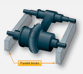
Check bushings that have been replaced to determine if the bushing and rod bores are square and parallel to each other. The alignment of a connecting rod can be checked several ways. One method requires a push fit arbor for each end of the connecting rod, a surface plate, and two parallel blocks of equal height.
To measure rod squareness, or twist, insert the arbors into the rod bores. [Figure 9] Place the parallel blocks on a surface plate. Place the ends of the arbors on the parallel blocks. Using a thickness gauge, check the clearance at the points where the arbors rest on the blocks. This clearance, divided by the separation of the blocks in inches, gives the twist per inch of length.
To determine bushing or bearing parallelism (convergence), insert the arbors in the rod bores. Measure the distance between the arbors on each side of the connecting rod at points that are equidistant from the rod centerline. For exact parallelism, the distances checked on both sides should be the same. Consult the manufacturer’s table of limits for the amount of misalignment permitted.
The preceding operations are typical of those used for most reciprocating engines and are included to introduce some of the operations involved in engine overhaul. It would be impractical to list all the steps involved in the overhaul of an engine. It should be understood that there are other operations and inspections that must be performed. For exact information regarding a specific engine model, consult the manufacturer’s overhaul manual.
Repair and Replacement
The engine components that have failed inspection, or are unrepairable, should have been discarded. The component parts that need repair and replacement are now given the attention required. The replacement components (new parts) are organized and laid out for reassembly.
Minor damage to engine parts, such as burrs, nicks, scratches, scoring, or galling, should be removed with a fine oil stone, crocus cloth, or any similar abrasive substance. Following any repairs of this type, the part should be cleaned carefully to be certain that all abrasive has been removed, and then checked with its mating part to assure that the clearances are not excessive. Flanged surfaces that are bent, warped, or nicked can be repaired by lapping to a true surface on a surface plate. Again, the part should be cleaned to be certain that all abrasive has been removed. Defective threads can sometimes be repaired with a suitable die or tap. Small nicks can be satisfactorily removed with Swiss pattern files or small, edged stones. Pipe threads should not be tapped deeper to clean them, because this practice results in an oversized tapped hole. If galling or scratches are removed from a bearing surface of a journal, it should be buffed to a high polished finish.
In general, welding of highly-stressed engine parts can be accomplished only when approved by the manufacturer. However, welding may be accomplished using methods that are approved by the engine manufacturer, and if it can be reasonably expected that the welded repair will not adversely affect the airworthiness of the engine.
Many minor parts not subjected to high stresses may be safely repaired by welding. Mounting lugs, cowl lugs, cylinder fins, rocker box covers, and many parts originally fabricated by welding are in this category. The welded part should be suitably stress-relieved after welding. However, before welding any engine part, consult the manufacturer’s instructions for the engine concerned to see if it is approved for repair by welding.
Parts requiring use of paint for protection or appearance should be repainted according to the engine manufacturer’s recommendations. Aluminum alloy parts should have original, exterior painted surfaces rubbed smooth to provide a proper paint base. See that surfaces to be painted are thoroughly cleaned. Care must be taken to avoid painting mating surfaces. Exterior aluminum parts should be primed first with a thin coat of zinc chromate primer. After the primer is dry, parts should be painted with engine enamel, that should be air dried until hard, or baked for 1⁄2 hour at 82 °C (180 °F). Aluminum parts from which the paint has not been removed may be repainted without the use of a priming coat, provided no bare aluminum is exposed.
Any studs that are bent, broken, damaged, or loose must be replaced. After a stud has been removed, the tapped stud hole should be examined for size and condition of threads. If it is necessary to re-tap the stud hole, it also is necessary to use a suitable oversize stud. Studs that have been broken off flush with the case must be drilled and removed with suitable stud remover. Be careful not to damage any threads. When replacing studs, coat the coarse threads of the stud with an anti-seize compound.
Cylinder Assembly Reconditioning
Cylinder and piston assemblies are inspected according to the procedures contained in the engine manufacturer’s manuals, charts, and service bulletins. A general procedure for inspecting and reconditioning cylinders is discussed in the following section to provide an understanding of the operations involved.
Visually inspect the head fins for other damage besides cracks. Dents or bends in the fins should be left alone unless there is danger of cracking. Where pieces of fin are missing, the sharp edges should be filed to a smooth contour. Fin breakage in a concentrated area causes dangerous local hot spots. Fin breakage near the spark plug bushings or on the exhaust side of the cylinder is obviously more dangerous than in other areas. When removing or re-profiling a cylinder fin, follow the instructions and the limits in the manufacturer’s manual.
Inspect spark plug inserts for the condition of the threads and for looseness. Run a tap of the proper size through the bushing. Very often, the inside threads of the bushing are burned. If more than one thread is missing, the bushing should be rejected. Tighten a plug in the bushing to check for looseness.
Piston and Piston Pins
If the old piston is to be reused, or a new piston is to be used, measure the outside of the piston by means of a micrometer. Measurements must be taken in several directions and on the skirt, as well as on the lands section. Check these sizes against the cylinder size. Most engines use cam ground pistons to compensate for the greater expansion parallel to the pin during engine operation. The diameter of these pistons measures several thousandths of an inch larger at an angle to the piston pin hole, than parallel to the pin hole. Inspect the ring grooves for evidence of wear. The groove needs to be checked for side clearance with a feeler gauge to determine the amount of wear in the grooves. Examine the piston pin for scoring, cracks, excessive wear, and pitting. Check the clearance between the piston pin and the bore of the piston pin bosses using a telescopic gauge and a micrometer. Use the magnetic particle method to inspect the pin for cracks. Since the pins are often case hardened, cracks show up inside the pin more often than they on the outside. Check the pin for bends using V-blocks and a dial indicator on a surface plate. [Figure 10] Measure the fit of the plugs in the pin. In many cases, the pistons and piston pins are routinely replaced at overhaul.
 |
| Figure 10. Checking a piston pin for bends |
Valves and Valve Springs
Critical areas of the valve include the face and tip [Figure 11], both of which should be examined for pitting and excessive wear. Minor pitting on valve faces can sometimes be removed by grinding. Be sure the valve guides are clean before inspection. Often, carbon covers pits inside the guide. If a guide in this condition is put back in service, carbon again collects in the pits and valve sticking results. Besides pits, scores, and burned areas inside the valve guide, inspect them for wear or looseness. Inspection of valve seat inserts before they are re-faced is mostly a matter of determining if there is enough of the seat left to correct any pitting, burning, scoring, or out-of-trueness.
 |
| Figure 11. Valve face surface |
Refacing Valve Seats
The valve seat inserts of aircraft engine cylinders usually are in need of refacing at every overhaul. They are refaced to provide a true, clean, and correct size seat for the valve. When valve guides or valve seats are replaced in a cylinder, the seats must be made concentric with the valve guide.
Low power engines can use either bronze or steel seats. Bronze seats, although not widely used on current engines, are made of aluminum bronze or phosphor bronze alloys. Steel seats are commonly used for valve seats on higher powered engines and are made of heat-resistant steel with a layer of stellite steel alloy on the valve contact surface. Stellite seats can require a special stone to grind this very hard material.
Steel valve seats are refaced by grinding equipment. [Figure 12] Bronze seats are refaced preferably by the use of cutters or reamers, but they may be ground when this equipment is not available. The only disadvantage of using a stone on bronze is that the soft metal loads the stone to such an extent that much time is consumed in redressing the stone to keep it clean.

The equipment used on steel seats can be either wet or dry valve seat grinding equipment. The wet grinder uses a mixture of soluble oil and water to wash away the chips and to keep the stone and seat cool; this produces a smoother, more accurate job than the dry grinder. The stones may be either silicon carbide or aluminum oxide.
Before refacing the seat, make sure that the valve guide is in good condition, clean, and does not have to be replaced. Mount the cylinder firmly in the hold down fixture. An expanding pilot is inserted in the valve guide from the inside of the cylinder, and an expander screw is inserted in the pilot from the top of the guide. [Figure 13] The pilot must be tight in the guide, because any movement can cause a poor grind. The fluid hose is inserted through one of the spark plug inserts.

The three grades of stones available for use are classified as rough, finishing, and polishing stones. The rough stone is designed to true and clean the seat. The finishing stone must follow the rough to remove grinding marks and produce a smooth finish. The polishing stone does just as the name implies and is used only where a highly polished seat is desired.
The stones are installed on special stone holders. The face of the stone is trued by a diamond dresser. The stone should be refaced whenever it is grooved or loaded, and when the stone is first installed on the stone holder. The diamond dresser also may be used to cut down the diameter of the stone. Dressing of the stone should be kept to a minimum as a matter of conservation; therefore, it is desirable to have sufficient stone holders for all the stones to be used on the job.
In the actual grinding job, considerable skill is required in handling the grinding gun. The gun must be centered accurately on the stone holder. If the gun is tilted offcenter, chattering of the stone results, and a rough grind is produced. It is very important that the stone be rotated at a speed that permits grinding instead of rubbing. This speed is approximately 8,000 to 10,000 revolutions per minute (rpm). Excessive pressure on the stone can slow it down. It is not a good technique to let the stone grind at slow speed by putting pressure on the stone when starting or stopping the gun. The maximum pressure used on the stone at any time should be no more than that exerted by the weight of the gun.
Another practice, conducive to good grinding, is to ease off on the stone every second or so to let the coolant wash away the chips on the seat. This rhythmic grinding action also helps keep the stone up to its correct speed. Since it is quite a job to replace a seat, remove as little material as possible during the grinding. Inspect the job frequently to prevent unnecessary grinding.
The rough stone is used until the seat is true to the valve guide and until all pits, scores, or burned areas are removed. [Figure 14] After refacing, the seat should be smooth and true. The finishing stone is used only until the seat has a smooth, polished appearance. Extreme caution should be used when grinding with the finishing stone to prevent chattering.

The size and trueness of the seat can be checked by several methods. Runout of the seat is checked with a special dial indicator and should not exceed 0.002 inch. The size of the seat may be determined by using Prussian blue. Prussian blue is used to check for contact transfer from one surface to the other. To check the fit of the seat, spread a thin coat of Prussian blue evenly on the seat. Press the valve onto the seat. The blue transferred to the valve indicates the contact surface. The contact surface should be one-third to two-thirds the width of the valve face and in the middle of the face. In some cases, a-go and no-go gauge is used in place of the valve when making the Prussian blue check. If Prussian blue is not used, the same check may be made by lapping the valve lightly to the seat. Lapping is accomplished by using a small amount of lapping compound placed between the valve face and seat. The valve is then moved in a rotary motion back and forth until the lapping compound grinds slightly into the surface. After cleaning the lapping contact compound off, a contact area can be seen. Examples of test results are shown in Figure 15.

If the seat contacts the upper third of the valve face, grind off the top corner of the valve seat. [Figure 16] Such grinding is called narrowing grinding. This permits the seat to contact the center third of the valve face without touching the upper portion of the valve face.

If the seat contacts the bottom third of the valve face, grind off the inner corner of the valve seat. [Figure 17] The seat is narrowed by a stone other than the standard angle. It is common practice to use a 15° angle and 45° angle cutting stone on a 30° angle valve seat, and a 30° angle and 75° angle stone on a 45° angle valve seat. [Figure 18]


If the valve seat has been cut or ground too much, the valve contacts the seat too far up into the cylinder head, and the valve clearance, spring tension, and the fit of the valve to the seat is affected. To check the height of a valve, insert the valve into the guide, and hold it against the seat. Check the height of the valve stem above the rocker box or some other fixed position.
Before refacing a valve seat, consult the overhaul manual for the particular model engine. Each manufacturer specifies the desired angle for grinding and narrowing the valve seat.
Valve Reconditioning
One of the most common jobs during engine overhaul is grinding the valves. The equipment used should preferably be a wet valve grinder. With this type of machine, a mixture of soluble oil and water is used to keep the valve cool and carry away the grinding chips.
Like many machine jobs, valve grinding is mostly a matter of setting up the machine. The following points should be checked or accomplished before starting a grind. True the stone by means of a diamond nib. The machine is turned on, and the diamond is drawn across the stone, cutting just deep enough to true and clean the stone. Determine the face angle of the valve being ground, and set the movable head of the machine to correspond to this valve angle. Usually, valves are ground to the standard angles of 30° or 45°. However, in some instances, an interference fit of 0.5° or 1.5° less than the standard angle may be ground on the valve face.
The interference fit is used to obtain a more positive seal by means of a narrow contact surface. [Figure 19] Theoretically, there is a line contact between the valve and seat. With this line contact, the load that the valve exerts against the seat is concentrated in a very small area, thereby increasing the unit load at any one spot. The interference fit is especially beneficial during the first few hours of operation after an overhaul. The positive seal reduces the possibility of a burned valve or seat that a leaking valve might produce. After the first few hours of running, these angles tend to pound down and become identical.

Notice that the interference angle is ground into the valve, not the seat. It is easier to change the angle of the valve grinder work head than to change the angle of a valve seat grinder stone. Do not use an interference fit unless the manufacturer approves it.
Install the valve into the chuck, and adjust the chuck so that the valve face is approximately 2 inches from the chuck. [Figure 20] If the valve is chucked any further out, there is danger of excessive wobble and also a possibility of grinding into the stem.

There are various types of valve grinding machines. In one type, the stone is moved across the valve face; in another, the valve is moved across the stone. Whichever type is used, the following procedures are typical of those performed when refacing a valve.
Check the travel of the valve face across the stone. The valve should completely pass the stone on both sides, yet not travel far enough to grind the stem. There are stops on the machine that can be set to control this travel.
With the valve set correctly in place, turn on the machine and the grinding fluid so that it splashes on the valve face. Back the grinding wheel off all the way. Place the valve directly in front of the stone. [Figure 21] Slowly bring the wheel forward until a light cut is made on the valve. The intensity of the grind is measured by sound more than anything else. Slowly draw the valve back and forth across the stone without increasing the cut. Move the work head table back and forth using the full face of the stone, but always keep the valve face on the stone. When the sound of the grind diminishes, indicating that some valve material has been removed, move the workhead table to the extreme left to stop rotation of the valve. Inspect the valve to determine if further grinding is necessary. If another cut must be made, bring the valve in front of the stone, then advance the stone out to the valve. Do not increase the cut without having the valve directly in front of the stone.

An important precaution in valve grinding, as in any kind of grinding, is to make light cuts only. Heavy cuts cause chattering, that may make the valve surface so rough that much time is lost in obtaining the desired finish.
After grinding, check the valve margin to be sure that the valve edge has not been ground too thin. A thin edge is called a feather edge and can lead to preignition; the valve edge would burn away in a short period of time, and the cylinder would have to be overhauled again. Figure 22 shows a valve with a normal margin and one with a feather edge.

The valve tip may be resurfaced on the valve grinder. The tip is ground to remove cupping or wear, and also to adjust valve clearances on some engines.
The valve is held by a clamp on the side of the stone. [Figure 23] With the machine and grinding fluid turned on, the valve is pushed lightly against the stone and swung back and forth. Do not swing the valve stem off either edge of the stone. Because of the tendency for the valve to overheat during this grinding, be sure plenty of grinding fluid covers the tip.

Grinding of the valve tip may remove, or partially remove, the bevel on the edge of the valve. To restore this bevel, mount a V-way approximately 45° to the grinding stone. Hold the valve onto the V-way and twist the valve tip onto the stone. With a light touch, grind all the way around the tip. This bevel prevents scratching the valve guide when the valve is installed.
Valve Lapping and Leak Testing
After the grinding procedure is finished, it is sometimes necessary that the valve be lapped to the seat. This is done by applying a small amount of lapping compound to the valve face, inserting the valve into the guide, and rotating the valve with a lapping tool until a smooth, gray finish appears at the contact area. The appearance of a correctly lapped valve is shown in Figure 24.

After the lapping process is finished, be sure that all lapping compound is removed from the valve face, seat, and adjacent areas. The final step is to check the mating surface for leaks to see if it is sealing properly. This is done by installing the valve in the cylinder, holding the valve by the stem with the fingers, and pouring kerosene or solvent into the valve port. While holding finger pressure on the valve stem, check to see if the kerosene is leaking past the valve into the combustion chamber. If it is not, the valve re-seating operation is finished. If kerosene is leaking past the valve, continue the lapping operation until the leakage is stopped. The incorrect indications are of value in diagnosing improper valve and valve seat grinding. Incorrect indications, their cause, and remedy are shown in Figure 25.
 |
| Figure 25. Incorrectly lapped valves |
Piston Repairs
Piston repairs are not required as often as cylinder repairs since most of the wear is between the piston ring and cylinder wall, valve stem and guide, and valve face and seat. A lesser amount of wear is encountered between the piston skirt and cylinder, ring and ring groove, or piston pin and bosses.
The most common repair is the removal of scores. Usually, these may be removed only on the piston skirt if they are very light. On engines where the entire rotating and reciprocating assembly is balanced, the pistons must weigh within one-fourth ounce of each other. When a new piston is installed, it must be within the same weight tolerance as the one removed. It is not enough to have the pistons matched alone; they must be matched to the crankshaft, connecting rods, piston pins, etc. To make weight adjustments on new pistons, the manufacturer provides a heavy section at the base of the skirt. To decrease weight, file metal evenly off the inside of this heavy section. The piston weight can be decreased easily, but welding, metalizing, or plating cannot be done to increase the piston weight.
If ring grooves are worn or stepped, the pistons are normally replaced. Small nicks on the edge of the piston pin boss may be sanded down. Deep scores inside the boss, or anywhere around the boss, are definite reasons for rejection. It has become more economical to replace pistons rather than reconditioning and reusing old ones, especially during overhaul.
Cylinder Grinding and Honing
If a cylinder has excessive taper, out-of-roundness, step, or its maximum size is beyond limits, it can be reground to the next allowable oversize. If the cylinder walls are lightly rusted, scored, or pitted, the damage may be removed by honing or lapping.
Regrinding a cylinder is a specialized job that the powerplant mechanic is not usually expected to be able to do. However, the mechanic must be able to recognize when a cylinder needs regrinding, and he or she must know what constitutes a good or bad job.
Generally, standard aircraft cylinder oversizes are 0.010 inch, 0.015 inches, 0.020 inch, or 0.030 inch. Aircraft cylinders have relatively thin walls and may have a nitrided surface, that must not be ground away. Nitriding is a surface hardening process that hardens the steel surface to a depth of several thousandths of an inch. Any one manufacturer usually does not allow all of the above oversizes. Some manufacturers do not allow regrinding to an oversize at all. The manufacturer’s overhaul manual, or parts catalog, usually lists the oversizes allowed for a particular make and model engine.
To determine the regrind size, the standard bore size must be known. This usually can be determined from the manufacturer’s specifications or manuals. The regrind size is figured from the standard bore. For example, a certain cylinder has a standard bore of 3.875 inches. To have a cylinder ground to 0.015 inches oversize, it is necessary to grind to a bore diameter of 3.890 inch (3.875 + 0.015). A tolerance of ±0.0005 inches is usually accepted for cylinder grinding.
Another factor to consider when determining the size to which a cylinder must be reground is the maximum wear that has occurred. If there are spots in the cylinder wall that are worn larger than the first oversize, then obviously it is necessary to grind to the next oversize to clean up the entire cylinder.
The type of finish desired in the cylinder is an important consideration when ordering a regrind. Some engine manufacturers specify a fairly rough finish on the cylinder walls, that allows the rings to seat even if they are not lapped to the cylinder. Other manufacturers desire a smooth finish to which a lapped ring seats without much change in ring or cylinder dimensions. The latter type of finish is more expensive to produce.
The standard used when measuring the finish of a cylinder wall is known as micro-inch root-meansquare (micro-inch rms). In a finish where the depth of the grinding scratches are one-millionth (0.000001) of an inch deep, it is specified as 1 microinch rms. Most aircraft cylinders are ground to a finish of 15 to 20 microinch rms. Several low-powered engines have cylinders that are ground to a relatively rough 20- to 30-microinch rms finish. On the other end of the scale, some manufacturers require a superfinish of approximately 4- to 6-microinch rms.
Cylinder grinding is accomplished by a firmly mounted stone that revolves around the cylinder bore, as well as up and down the length of the cylinder barrel. [Figure 26] The cylinder, the stone, or both may move to get this relative movement. The size of the grind is determined by the distance the stone is set away from the centerline of the cylinder. Some cylinder bore grinding machines produce a perfectly straight bore, while others are designed to grind a choked bore. A choked bore grind refers to the manufacturing process in which the cylinder walls arc ground to produce a smaller internal diameter at the top than at the bottom. The purpose of this type grind or taper is to maintain a straight cylinder wall during operation. As a cylinder heats up during operation, the head and top of the cylinder are subjected to more heat than the bottom. This causes greater expansion at the top than at the bottom, thereby maintaining the desired straight wall.
 |
| Figure 26. Cylinder bore grinding |
After grinding a cylinder, it may be necessary to hone the cylinder bore to produce the desired finish. In this case, specify the cylinder regrind size to allow for some metal removal during honing. The usual allowance for honing is 0.001 inch. If a final cylinder bore size of 3.890 inches is desired, specify the regrind size of 3.889 inches, and then hone to 3.890 inches.
There are several different makes and models of cylinder hones. The burnishing hone is used only to produce the desired finish on the cylinder wall. The more elaborate micromatic hone can also be used to straighten out the cylinder walls. A burnishing hone should not be used in an attempt to straighten cylinder walls. [Figure 27] Since the stones are only spring loaded, they follow the contour of the cylinder wall and may aggravate a tapered condition.

Deglazing the cylinder walls is accomplished with the use of a deglazing hone. A cross-hatch pattern must be placed on the cylinder wall to allow for piston ring break-in. This is accomplished by a deglazing hone turned by a drill being moved in and out of the cylinder rapidly. [Figure 28]

After the cylinders have been reground or deglazed, or both, check the size and wall finish, and check for evidence of overheating or grinding cracks before installing on an engine.