An emergency locator transmitter (ELT) is an independent battery-powered transmitter activated by excessive G-forces experienced during a crash. It transmits a digital signal every 50 seconds on a frequency of 406.025 MHz at 5 watts for at least 24 hours. The signal is received anywhere in the world by satellites in the Cospas-Sarsat satellite system.
Two types of satellites, low earth orbiting satellites (LEOSATs) and geostationary satellites (GEOSATs), are used with different, complementary capabilities. The signal is partially processed and stored by the satellites and then relayed to ground stations known as local user terminals (LUTs). Further processing of the signal takes place at the LUTs, and appropriate search and rescue operations are notified through mission control centers (MCCs) set up for this purpose.
The United States portion of the Cospas-Sarsat system is maintained and operated by National Oceanic and Atmospheric Administration (NOAA). Figure 1 illustrates the basic components in the Cospas-Sarsat system.
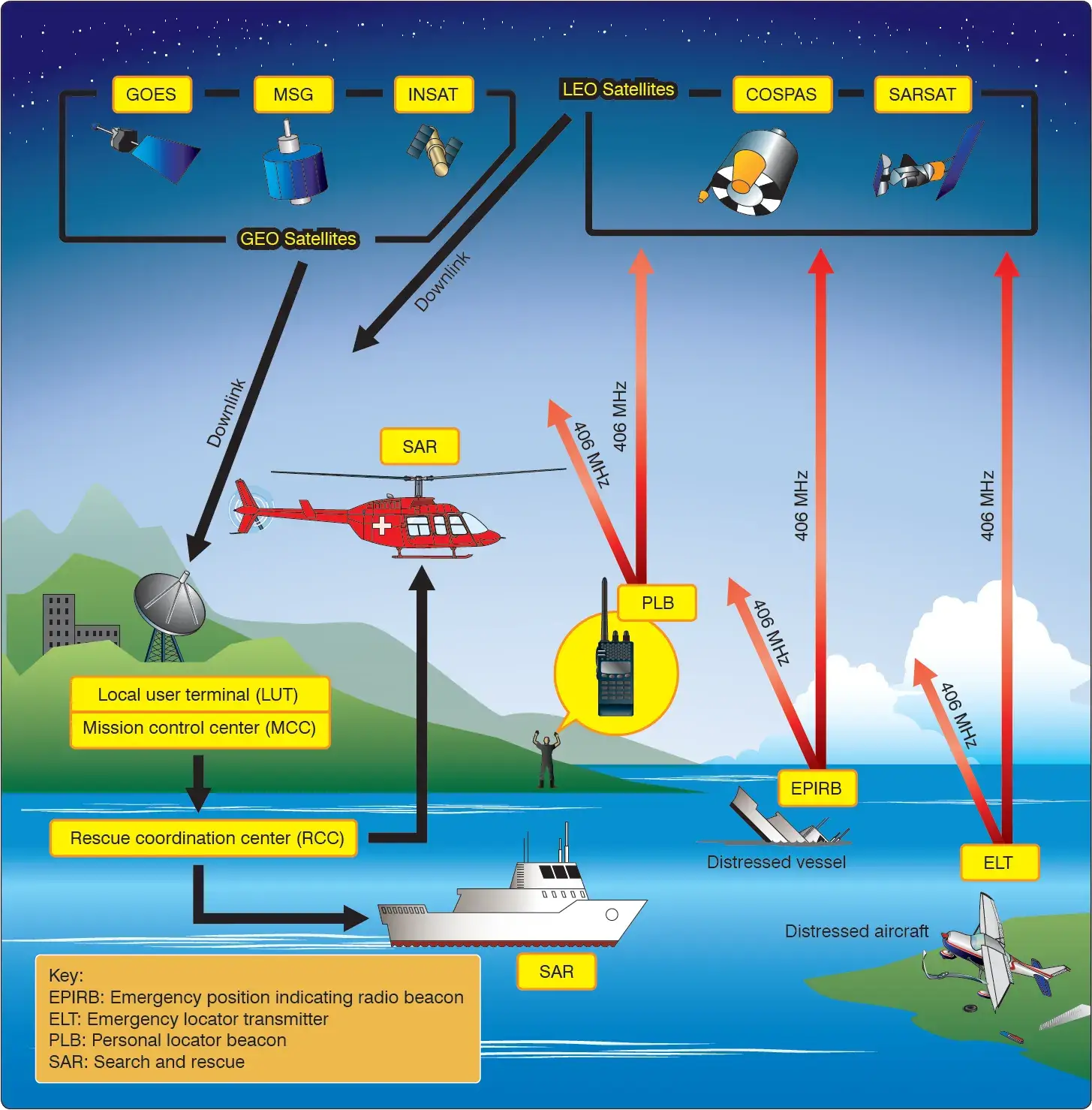 |
| Figure 1. The basic operating components of the satellite-based COSPAS-SARSAT rescue system of which aircraft ELTs are a part |
ELTs are required to be installed in aircraft according to 14 CFR §91.207. This encompasses most general aviation aircraft not operating under parts 135 or 121. ELTs must be inspected within 12 months of the previous inspection for proper installation, battery corrosion, operation of the controls and crash sensor, and the transmission of a sufficient signal at the antenna.
Built-in test equipment facilitates testing without transmission of an emergency signal. The remainder of the inspection is visual. Technicians are cautioned to not activate the ELT and transmit an emergency distress signal. Inspection must be recorded in maintenance records including the new expiration date of the battery. This must also be recorded on the outside of the ELT.
ELTs are typically installed as far aft in the fuselage of an aircraft as is practicable just forward of the empennage. The built-in G-force sensor is aligned with the longitudinal axis of the aircraft. Helicopter ELTs may be located elsewhere on the airframe. They are equipped with multidirectional activation devices. Follow ELT and airframe manufacturer’s instructions for proper installation, inspection, and maintenance of all ELTs. Figure 2 illustrates ELT mounting locations.
 |
| Figure 2. An emergency locator transmitter (ELT) mounting location is generally far aft in a fixed-wing aircraft fuselage in line with the longitudinal axis. Helicopter mounting location and orientation varies |
Use of Doppler technology enables the origin of the 406 MHz ELT signal to be calculated within 2–5 kilometers. Second generation 406 MHz ELT digital signals are encoded with GPS location coordinates from a receiver inside the ELT unit or integrated from an outside unit. This reduces the location accuracy of the crash site to within 100 meters.
The digital signal is also encoded with unique registration information. It identifies the aircraft, the owner, and contact information and other identifying data. When a signal is received, this is used to immediately research the validity of the alert to ensure it is a true emergency transmission so that rescue resources are not deployed needlessly.
ELTs with automatic G-force activation mounted in aircraft are easily removable. They often contain a portable antenna so that crash victims may leave the site and carry the operating ELT with them. A flight deck-mounted panel is required to alert the pilot if the ELT is activated. It also allows the ELT to be armed, tested, and manually activated if needed. [Figure 3]
 |
| Figure 3. An ELT and its components including a cockpitmounted panel, the ELT, a permanent mount antenna, and a portable antenna |
Modern ELTs may also transmit a signal on 121.5 MHz. This is an analog transmission that can be used for homing. Prior to 2009, 121.5 MHz was a worldwide emergency frequency monitored by the Cospas-Sarsat satellites. However, it has been replaced by the 406 MHz standard. Transmissions on 121.5 MHz are no longer received and relayed via satellite.
The FAA has not mandated the use of 406 MHz ELTs. An older 121.5 MHz ELT satisfies the requirements of 14 CFR §91.207 in all except new aircraft. Thousands of aircraft registered in the United States remain equipped with ELTs that transmit a 0.75-watt analog 121.5 MHz emergency signal when activated. The 121.5 MHz frequency is still monitored by overflying aircraft and control towers, although it is no longer monitored by satellites.
Technicians are required to perform an inspection/test of 121.5 MHz ELTs within 12 months of the previous inspection and inspect for the same operational integrity as required for the 406 MHz ELTs mentioned above. However, older ELTs often lack the built-in test circuitry of modern ELTs certified to TSO C-126. Therefore, a true operational test may include activating the signal.
This can be done by removing the antenna and installing a dummy load. Any activation of an ELT signal is required to be performed only between the top of each hour and 5 minutes after the hour. The duration of activation must be no longer than three audible sweeps. Contacting the local control tower or flight service station before testing is recommended.
It must be noted that older 121.5 MHz analog signal ELTs often also transmit an emergency signal on a frequency of 243.0 MHz. This has long been the military emergency frequency. Its use is being phased out in favor of digital ELT signals and satellite monitoring.
Testing the functionality of a 121.5 MHz transmitter should be accomplished per manufacturer’s instructions. Improvements in coverage, location accuracy, identification of false alerts, and shortened response times are so significant with 406 MHz ELTs, they are currently the international service standard.
Testing Considerations for 406 MHz ELTs
Care should be taken to prevent accidentally triggering a search and rescue (SAR) response. Accidental activation of an ELT will generate an emergency signal that cannot be distinguished from that of an actual emergency and could lead to expensive and frustrating searches.
Moreover, the unwarranted ELT signal could tie up the emergency frequencies such that a genuine emergency signal would not be detected. In addition, if an ELT signal is transmitted on or near an airport, it may render some radio communications channels unusable.
Regardless of where the ELT is, or the duration of activation, a 406 MHz beacon broadcast will be detected by at least one Geostationary Local User Terminal (GEOLUT) and possibly every Low Earth Orbit Local User Terminal (LEOLUT) in the Cospas-Sarsat System.
Alert messages will be routed to every Mission Control Center (MCC) in the Cospas-Sarsat System for coordination around the world and a response will be initiated (unless prior coordination is made with Cospas-Sarsat and local authorities).
Direct-connection testing is preferred to prevent inadvertent activation of the SAR response system. Over-the-air testing should always be avoided if possible. Use of an antenna boot or a direct connection from test equipment to the antenna port is preferred.
Testing an ELT system in a metal hangar will not guarantee that the radiated signal will remain undetected by the Cospas-Sarsat System. Technicians testing ELT devices in a hangar should treat the test as if they were testing outside.
When testing an ELT, a 50-ohm dummy load or antenna boot should be used to prevent the signal from being radiated into space. The signal must be attenuated to less than −51 dBW, corresponding to a power flux density below −37.4 dBW/m² or a field intensity below −11.6 dBV/m.
If over-the-air testing must be accomplished, technicians should carefully follow Cospas-Sarsat instructions and use the built-in test message on the ELT device. The ELT test message is different from messages transmitted during an emergency, but is still detectable by the Cospas-Sarsat System.
Cospas-Sarsat should be contacted prior to performing over-the-air testing. Additional information is available from the Cospas-Sarsat website. If over-the-air testing must be accomplished, the local air traffic control (ATC) facility should be contacted in advance.
Follow test set instructions or place the test set a minimum of 12 meters (39.4 feet) from the ELT antenna. Test each mode and frequency on which the ELT transmits.
406 MHz Testing
Verify the device is outputting a signal of not less than 17 dBm (50 mW) and not greater than 26 dBm (400 mW).
Verify the device is transmitting on the correct frequency. This can be done by running the ELT self-test and detecting the signal with an ELT test set. Receiving and decoding a test message is an indication that the unit is transmitting on the correct frequency.
Using appropriate test equipment and shielding, note the ELT code transmitted and verify that the ELT code is registered with Cospas-Sarsat. The testing technician or aircraft owner should verify the information registered with Cospas-Sarsat is accurate and up to date.
Determine that the ELT aural indicator can be heard in the flight deck with the aircraft engines shut down, and that the visual indicator can be seen from the crew’s normal sitting position. If possible, this should be performed in a way that will prevent a SAR response (e.g., with a dummy load installed).
Perform an operational check of the G-switch. This should be performed in a way that will prevent a SAR response (e.g., with a dummy load installed). Replace the G-switch if it fails to activate.
Ensure all cables are reconnected except the 406 MHz transmitter output, which should remain connected to the test set if possible. Activate the ELT (use the remote switch if installed) and determine if the system is transmitting a valid 406 MHz signal. Ensure the system is reset if necessary.
If equipped with a water-activated circuit, connect the ELT to a test set if possible. Activate the ELT by shorting the water-sensing leads and determine if the system is transmitting a valid 406 MHz signal. Ensure the system is reset if necessary.
What is the advantage of a 406 MHz ELT over older 121.5 MHz units?
How often must an aircraft ELT be inspected?
How can technicians prevent accidental SAR alerts during a 406 MHz test?
What are the specific requirements for testing a 121.5 MHz ELT signal?
RELATED POSTS